
Water flow control device, condensate water collecting cup and breathing machine

A water flow control and collection cup technology, applied in the field of medical devices, can solve the problems of secondary infection of patients, increased incidence of ventilator-associated pneumonia, unhygienic and other problems

Pending Publication Date: 2018-08-10
佘小斌 +1
View PDF10 Cites 0 Cited by
  • Summary
  • Abstract
  • Description
  • Claims
  • Application Information

AI Technical Summary

Problems solved by technology

At the same time, condensed water is conducive to the reproduction of bacteria. If it is not cleaned up in time, the bacteria will flow to the patient's airway, which will increase the incidence of ventilator-associated pneumonia and increase the mortality of patients.
[0003] In clinical nursing work, the staff generally remove the water collection cup manually and dump the condensed water, which is not only unhygienic and unsafe, but also has a very heavy workload, because the condensed water is caused by the condensation of hot and humid gas in the patient's respiratory tract. It may contain pathogenic substances such as bacteria, which may easily cause secondary infection of patients

Method used


Image

  • Water flow control device, condensate water collecting cup and breathing machine
  • Water flow control device, condensate water collecting cup and breathing machine
  • Water flow control device, condensate water collecting cup and breathing machine

Examples


Embodiment approach

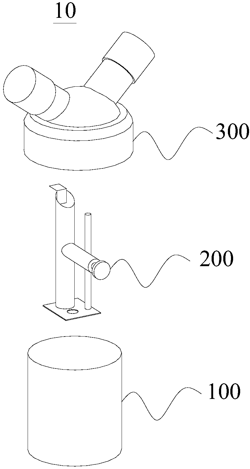
[0043] As an implementation manner, the first cylinder 210 is a solid structure, and the second cylinder 220 is a hollow structure.

[0044] As an implementation manner, the elastic member 265 may be a spring.

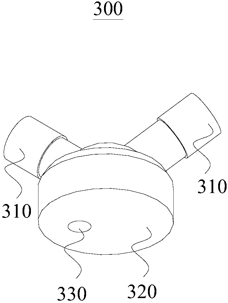
[0045] As an implementation, in order to make the first cylinder 210 move to the first drain port 330, the water discharged from the first drain port 330 can enter the collection cup 100, the first The plane of the cross-section of the end of the cylinder 210 close to the cup cover 300 is not parallel to the plane of the isolation plate 320 .

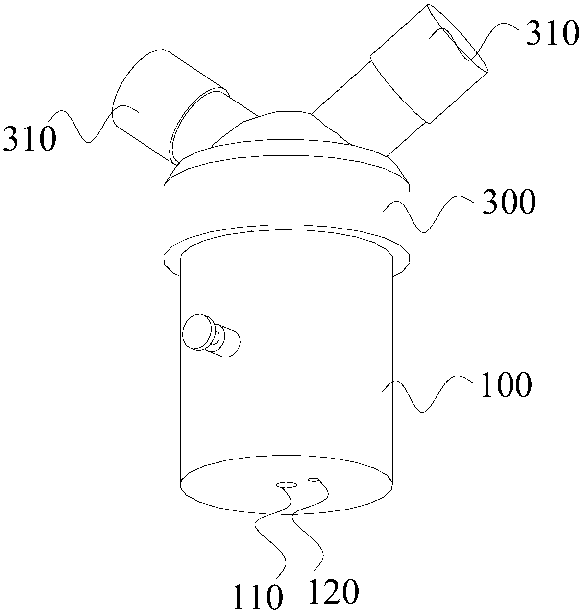
[0046] exist Figure 4 , the push cover 264 compresses the elastic member 265 under the push of an external force, until the push cover 264 fits the sleeve 262, and the first through hole 245 just moves to the second drain port 110, the second through hole moves to the position of the vent 120, at this time, the first drainage port 330 is blocked by the first sheet 230, and the second column is located at the second At the po...


PUM


Abstract

The embodiment of the invention provides a water flow control device, a condensate water collecting cup and a breathing machine. The water flow control device comprises a water flow control assembly and a driving part. The water flow control assembly comprises a first column, a second column, a first slice and a second slice, wherein the first column is arranged in the collecting cup in the extending direction of the collecting cup, the first slice is fixedly connected with the side wall at the end, close to a cup cover, of the first column, and is attached to a separator, the second slice isfixedly connected with the end, close to the bottom of the collecting cup, of the first column, and is attached to the bottom of the collecting cup, a first through hole and a second through hole which is used for being communicated with the second column are formed in the second slice. One end of the driving part penetrates through the collecting cup and is connected with the first column, the other end extends outside the collecting cup, and the driving part is used for driving the water flow control assembly to move under the action of external force. Therefore, the condensate water treatment safety is improved, medical workers and patients are prevented from being infected by germs, and the water flow control device is safer and more reliable in use.

Description

technical field [0001] The invention relates to the field of medical equipment, in particular to a water flow control device, a condensed water collection cup and a ventilator. Background technique [0002] In modern clinical medicine, the ventilator, as an effective means of artificially replacing the spontaneous ventilation function, has been widely used in respiratory failure caused by various reasons, anesthesia respiratory management during major surgery, respiratory support treatment and emergency resuscitation. It occupies a very important position in the field of modern medicine. Ventilator is a vital medical equipment that can prevent and treat respiratory failure, reduce complications, save and prolong the life of patients. When most hospitals use ventilators, they use active heating humidifiers to increase the humidity and temperature of the gas inhaled by patients. Since the ambient temperature is generally lower than the gas temperature in the ventilator pipeli...

Claims


Application Information

Patent Timeline
Patent Type & Authority Applications(China)
IPC IPC(8): A61M16/08
CPCA61M16/0003A61M16/0808A61M2205/3379
Inventor 佘小斌赵永辉
Owner 佘小斌
Learn More