Electromagnetic type jigging machine

A jigger and electromagnetic technology, which is applied in solid separation, wet separation, chemical instruments and methods, etc., can solve the problems of field workers' auditory system damage, jig vibration, short service life, etc., and achieve noise reduction. Small, small vibration, and the effect of reducing the damage of the auditory system

Inactive Publication Date: 2018-08-10
SICHUAN DONGLIN MINE TRANSPORT MACHINERY
View PDF0 Cites 2 Cited by
  • Summary
  • Abstract
  • Description
  • Claims
  • Application Information

AI Technical Summary

Problems solved by technology

[0004] The existing jigging machine generally adopts the structure connected with the cone bucket through the cam. The cam makes the cone bucket rise and fall quickly to realize the fluid of the vertical alternating medium so that the minerals can be re-stratified. The jig vibration is relatively large during the washing process. High, it is easy to cause damage to the equipment, the service life is short, and it will generate a lot of noise during the production process, which will cause damage to the auditory system of the on-site staff

Method used


Image

  • Electromagnetic type jigging machine
  • Electromagnetic type jigging machine

Examples


Embodiment 1

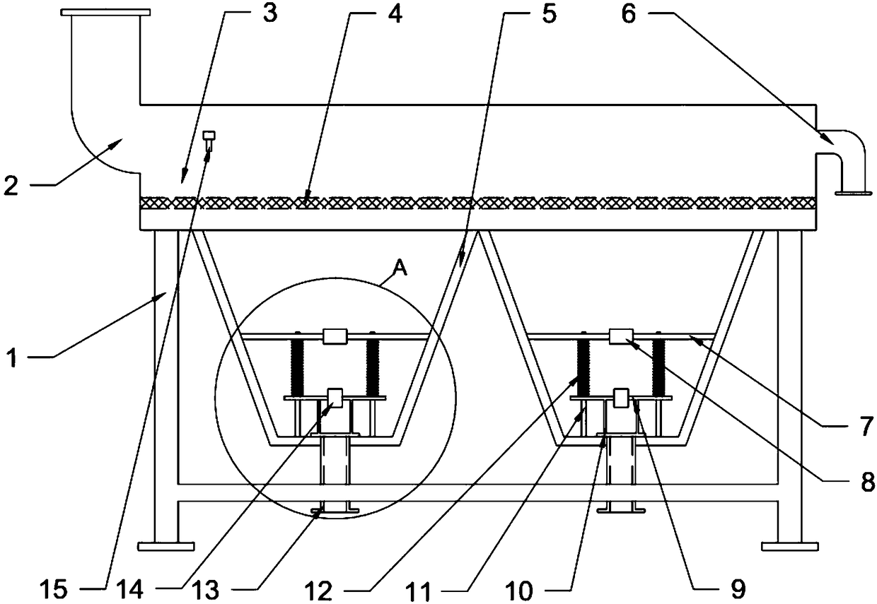
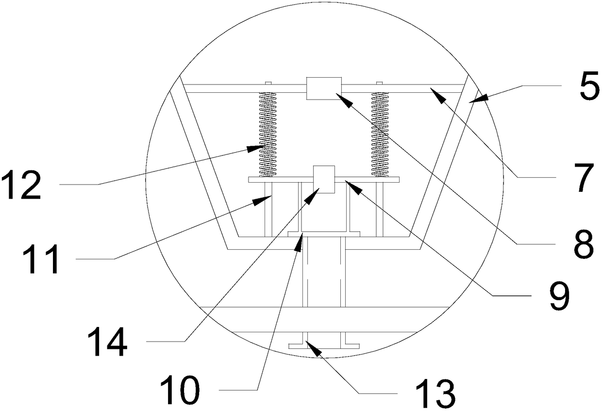
[0028] see figure 1 , an electromagnetic jig, comprising a frame 1, a slot 3 is installed above the frame 1, a feeding pipe 2 is installed at one end of the slot 3, and a discharge port 6 is installed at the other end, the bottom of the slot 3 is connected to the two A cone bucket 5 is connected, and a bracket 7 is installed inside the cone bucket 5, an electromagnet 8 is installed on the bracket 7, a slide bar 11 is connected with the bottom of the cone bucket 5 downward on the bracket 7, and a shock plate 9 is arranged below the bracket 7, and the shock plate 9 is provided with a positioning hole through which the slide bar 11 passes, and the inner wall surface of the positioning hole is attached to the outer wall surface of the slide bar 11 , and a magnet 14 is installed on the shock plate 9 .

[0029] In this example, the raw coal is crushed and sieved and mixed with water, and flows into the passage 3 on the frame 1 through the feed pipe 2, and the electromagnet 8 in the ...

Embodiment 2

[0031] see figure 1 , an electromagnetic jig, comprising a frame 1, a slot 3 is installed above the frame 1, a feeding pipe 2 is installed at one end of the slot 3, and a discharge port 6 is installed at the other end, the bottom of the slot 3 is connected to the two A cone bucket 5 is connected, and a bracket 7 is installed inside the cone bucket 5, an electromagnet 8 is installed on the bracket 7, a slide bar 11 is connected with the bottom of the cone bucket 5 downward on the bracket 7, and a shock plate 9 is arranged below the bracket 7, and the shock plate 9 is provided with a positioning hole through which the slide bar 11 passes, and the inner wall surface of the positioning hole is attached to the outer wall surface of the slide bar 11 , and a magnet 14 is installed on the shock plate 9 .

[0032] There is a row of ore openings at the bottom of the cone bucket 5, and an ore discharge pipe 13 is connected to the bottom of the ore discharge opening. The denser mineral pa...

Embodiment 3

[0034] see figure 1 , an electromagnetic jig, comprising a frame 1, a slot 3 is installed above the frame 1, a feeding pipe 2 is installed at one end of the slot 3, and a discharge port 6 is installed at the other end, the bottom of the slot 3 is connected to the two A cone bucket 5 is connected, and a bracket 7 is installed inside the cone bucket 5, an electromagnet 8 is installed on the bracket 7, a slide bar 11 is connected with the bottom of the cone bucket 5 downward on the bracket 7, and a shock plate 9 is arranged below the bracket 7, and the shock plate 9 is provided with a positioning hole through which the slide bar 11 passes, and the inner wall surface of the positioning hole is attached to the outer wall surface of the slide bar 11 , and a magnet 14 is installed on the shock plate 9 .

[0035] Oscillating plate 9 is downwardly connected with ore discharge baffle 10, and ore discharge baffle 10 can block the ore discharge outlet, reduce the amount of replenishing wa...


PUM


Abstract

The invention relates to the field of coal mining equipment, in particular to an electromagnetic type jigging machine. The electromagnetic type jigging machine comprises a machine frame, a passing tank is installed above the machine frame, an ore supply pipe is installed at one end of the passing tank, and a discharge outlet is formed in the other end of the passing tank; the bottom of the passingtank communicates with two taper hoppers; and supports are installed inside the taper hoppers and provided with electromagnets, the supports are downwards connected with the bottoms of the taper hoppers through sliding rods, a vibrating plate is arranged below each support and provided with positioning holes allowing the corresponding sliding rods to penetrate through, the inner walls of the positioning holes are attached to the outer walls of the sliding rods, and magnets are installed on the vibrating plates. According to the electromagnetic type jigging machine, vibration is carried out inside the taper hoppers by effectively adopting an electromagnetic vibrating mode, and washing is conducted on coal mine through vertical alternating medium fluid; and compared with the traditional mode that the taper hoppers vibrate by adopting a cam to achieve the vertical alternating medium fluid, vibration is small, the machine is not prone to being damaged, the service life of the machine is prolonged, noise generated in the production process is low, and harm to the auditory system of field personnel is reduced.

Description

technical field [0001] The invention relates to the field of coal mine equipment, in particular to an electromagnetic jig. Background technique [0002] After coal is mined, it will generally go through a washing process. Coal washing generally refers to the process of removing gangue or other impurities from coal. The physical properties of coal and rock are used to make coal and gangue ( impurities) are separated. Coal washing can improve coal quality, reduce coal-burning pollutant emissions, improve coal utilization efficiency, save energy, optimize product structure, improve product competitiveness, and reduce transportation cost. [0003] At present, jigging is the most mainstream coal washing method. The materials are mainly sorted according to the density difference in the vertically ascending and variable medium flow, and the minerals can be re-stratified under the action of the vertical alternating medium flow. The mineral particles with higher density settle quic...

Claims


Application Information

Patent Timeline
Patent Type & Authority Applications(China)
IPC IPC(8): B03B5/10B03B5/24
CPCB03B5/10B03B5/24
Inventor 肖先林袁波陈智能刘刚
Owner SICHUAN DONGLIN MINE TRANSPORT MACHINERY
Why Eureka
Try Eureka