Plate cutting-off device for building

A cutting device and construction technology, which is applied in the direction of shearing devices, accessories of shearing machines, maintenance and safety accessories, etc., can solve the problems of uneven cutting of building materials, waste of resources, and single function, so as to reduce production funds and ensure The effect of cutting neatly and reducing manpower and material resources

Active Publication Date: 2018-08-10
长乐智睿恒创节能科技有限责任公司
View PDF10 Cites 3 Cited by
  • Summary
  • Abstract
  • Description
  • Claims
  • Application Information

AI Technical Summary

Problems solved by technology

[0003] In the prior art, the patent number is CN206326370U, and the name is a patent for a plate cutting device. This patent has a good cutting function, but the protection function is lacking.
[0004] In the processing fields such as building materials, the cutting device is an indispensable part. The quality of cutting directly determines the quality of the final product. Now the cutting devices on the market often have a single function, and the processing process requires manpower, which is inconvenient. In addition, the current Some cutting devices are not stable enough to be fixed as a whole, which will lead to uneven or unstable cutting of building materials, which is prone to waste of materials, and not only large-scale construction sites, but also the tree and building materials market, because small wood cannot be cut uniformly , the occurrence of cutting defects directly causes the waste of resources, so it is necessary to design a cutting device for building plates

Method used


Image

  • Plate cutting-off device for building
  • Plate cutting-off device for building

Examples


Embodiment Construction

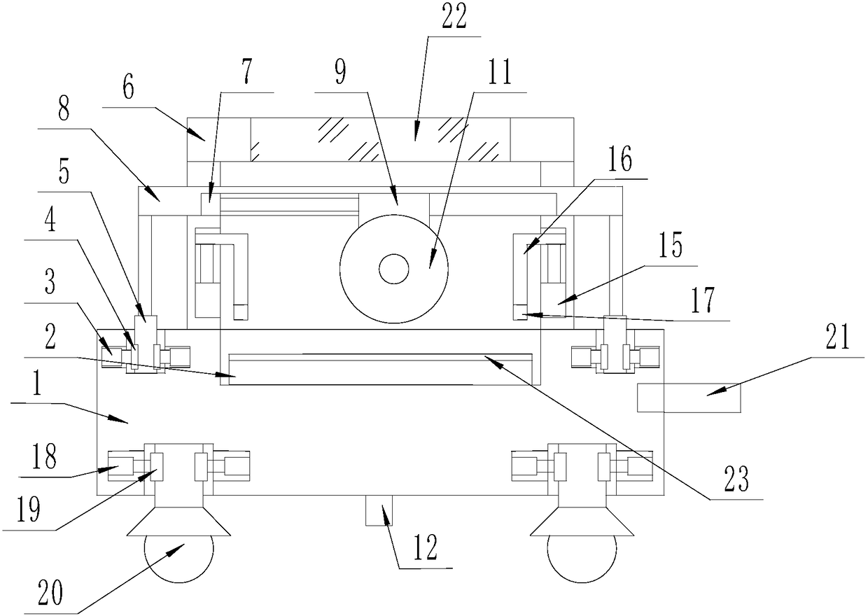
[0017] The present invention is specifically described below in conjunction with accompanying drawing, as Figure 1-2 As shown, a construction board cutting device includes a base 1, a strip-shaped groove is processed at the center of the upper surface of the base 1, and a conveyor belt 2 is embedded in the strip-shaped groove, and the upper surface of the base 1 is located on the conveyor belt. 2 No. 1 circular grooves are processed on both sides, and No. 2 circular grooves are processed on the circumference surfaces of both sides of each No. 1 circular groove, and each No. 2 circular groove is embedded with The telescopic end is the No. 1 electronically controlled telescopic rod 3 that is horizontal, and the side surface of each telescopic end of the No. Install the No. 1 linear motor 5 with the telescopic end upward. The upper surface of the base 1 and the middle of the pair of No. 1 linear motors 5 are provided with a door-shaped frame 6. The surfaces of both sides of the ...


PUM


Abstract

The invention discloses a plate cutting-off device for a building. The plate cutting-off device comprises a base, a strip-shaped open groove is machined in the center of the upper surface of the base,a conveying belt is embedded in the strip-shaped open groove, and first circular grooves are formed in the position, on the two sides of the conveying belt, of the upper surface of the base; second circular grooves are formed in the circumferential faces of the two sides of each first circular groove correspondingly, a first electrically controlled telescopic rod with the horizontal telescopic end is mounted in each second circular groove in an embedded mode, a semicircular clamping plate is arranged on the side surface of the telescopic end of each first electrically controlled telescopic rod, and a first linear motor with the upward telescopic end is mounted in each first circular groove in an embedded mode; and a gantry-type frame is arranged on the position, in the middle of the pairof first linear motors, of the upper surface of the base; and rectangular open grooves are formed in the surfaces of the two sides of the gantry-shaped frame correspondingly, rectangular plates are arranged on the upper surfaces of the telescopic ends of the pair of first linear motors, and strip-shaped sliding channels are formed in the lower surfaces of the rectangular plates. The plate cutting-off device for the building has the beneficial effects of simple structure and high practicability.

Description

technical field [0001] The invention relates to the construction field, in particular to a construction board cutting device. Background technique [0002] With the development of the modern mechanical processing industry, the requirements for cutting quality and precision are constantly improving, and the requirements for improving production efficiency, reducing production costs, and highly intelligent automatic cutting functions are also increasing. The development of CNC cutting machines must adapt to the requirements of the development of modern machining industry. Cutting machine is divided into flame cutting machine, plasma cutting machine, laser cutting machine, water cutting and so on. The laser cutting machine has the fastest efficiency, the highest cutting precision, and the cutting thickness is generally small. The cutting speed of the plasma cutting machine is also very fast, and the cutting surface has a certain slope. The flame cutting machine is aimed at t...

Claims


Application Information

Patent Timeline
Patent Type & Authority Applications(China)
IPC IPC(8): B23D19/00B23D33/02B23D33/12B23Q11/00
CPCB23D19/00B23D33/02B23D33/12B23Q11/005
Inventor 高博
Owner 长乐智睿恒创节能科技有限责任公司
Why Eureka
Try Eureka