Eureka AIR delivers breakthrough ideas for toughest innovation challenges, trusted by R&D personnel around the world.

Cooling liquid recovering device for worm gear machining

A recovery device and coolant technology, applied in the direction of worm gear, metal processing equipment, metal processing machinery parts, etc., can solve the problems of polluting the environment, cumbersome steps, increasing the workload of workers, etc., to reduce workload, reduce pollution, and save costs Effect

Inactive Publication Date: 2018-08-10
芜湖市诚信锌合金有限公司
View PDF0 Cites 1 Cited by
  • Summary
  • Abstract
  • Description
  • Claims
  • Application Information

AI Technical Summary

Problems solved by technology

[0003] At present, when processing worm gears, worm gear hobs are generally used for milling on milling machines. During milling, coolant is generally sprayed on the cutter head to cool the cutters, so as to avoid damage to the cutters due to overheating and prolong the service life. The collection box is used to collect the cooling liquid, but the collected cooling liquid contains more debris. If the cooling liquid needs to be reused, the collected cooling liquid needs to be filtered additionally. The steps are cumbersome and increase The workload of the workers, and the metal scraps cannot be recycled, pollute the environment, and increase the cost of worm gear processing. Therefore, in view of the above problems, a cooling liquid recovery device for worm gear processing is proposed

Method used


Image

  • Cooling liquid recovering device for worm gear machining
  • Cooling liquid recovering device for worm gear machining
  • Cooling liquid recovering device for worm gear machining

Examples


Embodiment Construction

[0018] The following will clearly and completely describe the technical solutions in the embodiments of the present invention with reference to the accompanying drawings in the embodiments of the present invention. Obviously, the described embodiments are only some, not all, embodiments of the present invention. Based on the embodiments of the present invention, all other embodiments obtained by persons of ordinary skill in the art without making creative efforts belong to the protection scope of the present invention.

[0019] see Figure 1-3 , the present invention provides a technical solution:

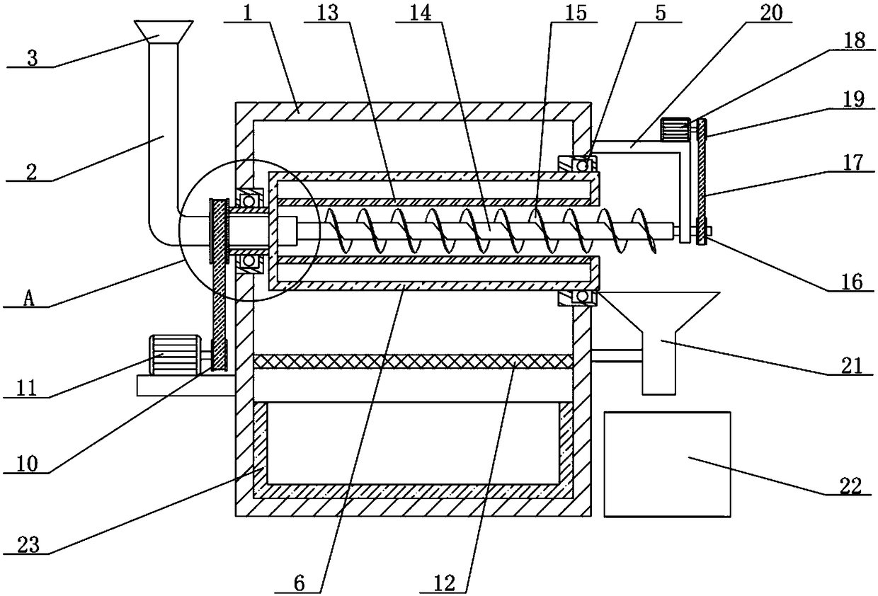
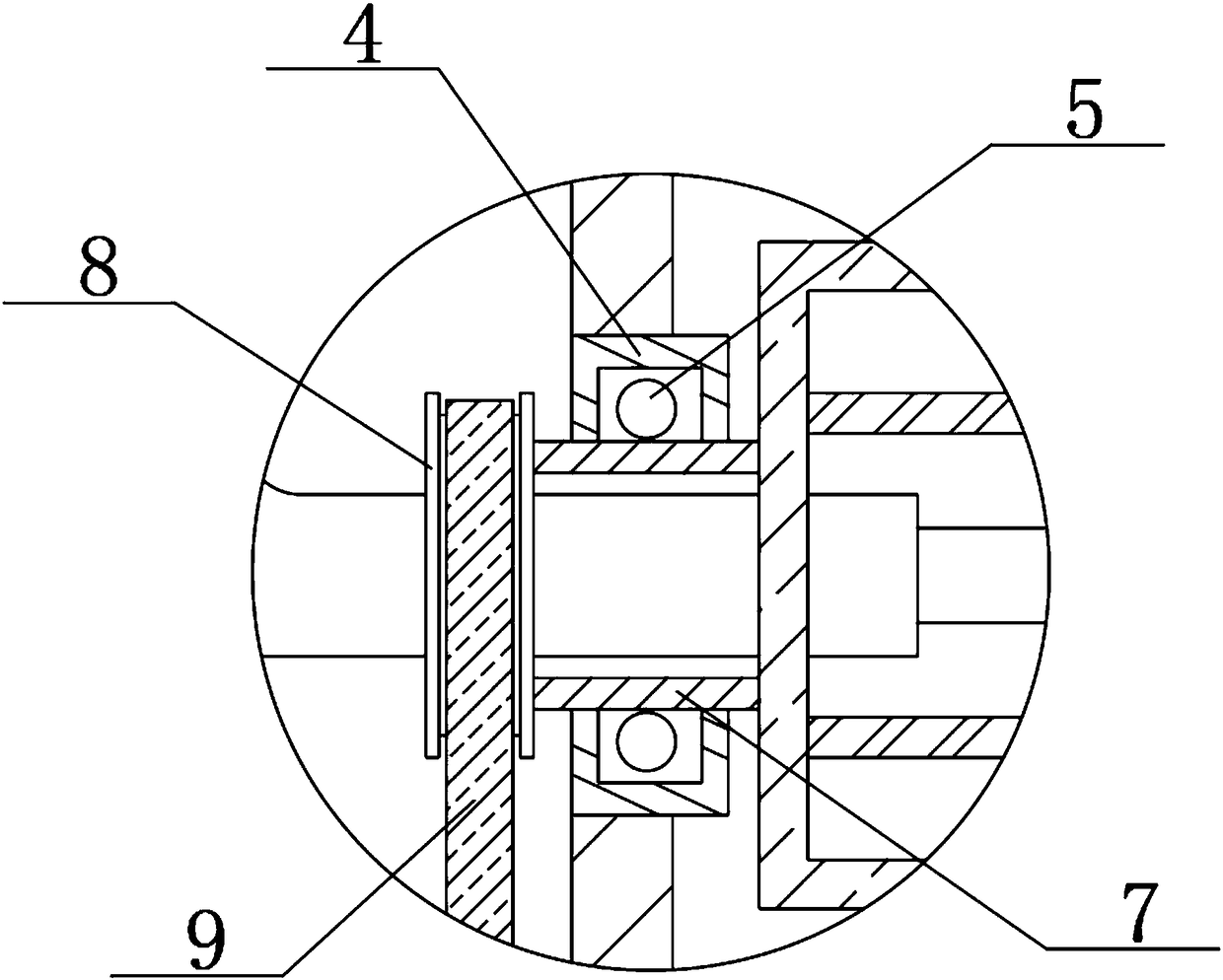
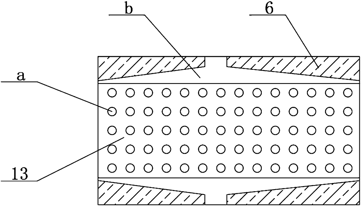
[0020] A coolant recovery device for worm gear processing, comprising a housing 1, a liquid inlet 3 at the left end of the housing 1, a liquid inlet pipe 2 below the liquid inlet 3, and a recovery box 22 on the right side of the housing 1, the housing 1 The left and right side walls are fixedly connected with fixing seats 4, and there is a channel in the middle of the left and rig...


PUM


Abstract

The invention relates to the technical field of recovering equipment, in particular to a cooling liquid recovering device for worm gear machining. The cooling liquid recovering device comprises a shell, a liquid inlet hopper at the left end of the shell, a liquid inlet pipe below the liquid inlet hopper and a recovering box on the right side of the shell, fixing bases are fixedly connected to theleft and right side walls of the shell, a channel is formed between the left and right fixing bases, an outer pipe body which is horizontally arranged inside the shell, a connecting part is fixedly connected to the left end of the outer pipe body, a second belt wheel is fixedly connected to the outer side of the left end of the connecting part, a filtering net is arranged under the outer pipe body, an inner pipe body is fixedly connected to the interior of the outer pipe body, a rotating rod is arranged in the middle of the inner pipe body horizontally, a spiral blade is fixedly connected to the rotating rod, and the right end of the rotating rod penetrates out of the shell to be fixedly connected with a fourth belt wheel. The cooling liquid recovering device is compact in stricture, continuous in operation and stable in running, cooling liquid can be effectively filtered, filtering objects can be recycled, the huge economical benefit and the wide market requirement are achieved, and the device is worthy of popularization.

Description

technical field [0001] The invention relates to the technical field of recovery equipment, in particular to a cooling liquid recovery device for worm gear processing. Background technique [0002] Worm gear processing, worm gear is a kind of gear that meshes with the worm and has a special tooth shape. The cutting of the worm gear is generally completed by a gear hobbing machine. There are mainly two methods of gear hobbing and flying knife cutting. When manufacturing precision worm gears, hobbing Or after cutting the teeth, carry out finishing processing such as shaving, honing or grinding. Using worm gear transmission can obtain a large transmission ratio, which is more compact than the cross-axis helical gear mechanism. The meshing tooth surfaces of the two wheels are in line contact. Much higher than the cross-axis helical gear mechanism, the worm transmission is equivalent to the screw transmission, which is a multi-teeth meshing transmission, so the transmission is sta...

Claims


Application Information

Patent Timeline
Patent Type & Authority Applications(China)
IPC IPC(8): B23F11/00B23Q11/10
CPCB23F11/00B23Q11/1069
Inventor 不公告发明人
Owner 芜湖市诚信锌合金有限公司
Why Eureka
Eureka Blog
Learn More