Push-fit valve with integrated mounting assembly

a technology of mounting assembly and push-fit valve, which is applied in the direction of valve housing, coupling, transportation and packaging, etc., can solve the problems of pipe fittings being tampered with, unable to allow piping assemblies, damage or induce wear on parts, etc., and achieves the effect of convenient connection, mounting, dismounting, and repair and reuse of piping system parts

Inactive Publication Date: 2011-05-17
QUICK FITTING
View PDF4 Cites 65 Cited by
  • Summary
  • Abstract
  • Description
  • Claims
  • Application Information

AI Technical Summary

Benefits of technology

[0009]The present invention provides, in part, a push-fit valve and integrated mounting assembly that facilitates the connection, mounting, dismounting, repair and re-use of piping system parts. The present invention can be employed with residential and commercial plumbing in bathroom, kitchens, laboratories and other areas incorporating fluid handling. The present invention eliminates the requirement for in-wall preparation or stub-out mounting by providing a complete push connect valve assembly that is mounted directly to the supply tubing, and then mounted to the wall utilizing mounting of lag screws. Unlike the conventional methods, the mounted assembly can be easily removed, repaired and reused.
[0010]The present invention provides an integrated valve, push connection and push release components, and a valve mounting assembly for use on fluid, air or gas applications. The invention allows for the installation of the valve by sliding the valve over the supply tube / piping or pushing the tube / piping into the valve. Once connected, an o-ring seals the connection, a packing gland applies energy to the o-ring seal maintaining constant, even pressure across the seal, and a grip ring applies opposing energy to prevent the disconnection of the assembly. The quick connection assembly is retained by a retaining cap, which applies constant, positive force on the sealing surface. A leak-free seal is created in seconds without any glue, soldering, compression, welding or tools. Once connected, the user may mount the assembly to a wall or surface utilizing the integrated valve mounting plate and mounting screws. To dismount the assembly, the user can remove the mounting screws, grip the dismounting plate and apply force toward the valve. The dismounting plate applies force to the grip ring, removing its grip from the supply tube or pipe. The user then pulls the valve from the supply while holding the pressure on the dismounting plate. The assembly is reusable and / or repairable by removing the threaded retaining cap to expose the sealing mechanism. The final installation can include an escutcheon or wall plate to dress the final assembly. This escutcheon can optionally be integrated into the final assembly of the valve.
[0012]In another aspect, the present invention comprises a dismountable valve that is easily removed and reused by removing the wall mounting screws, then depressing the mounting plate to relieve the grip of the internal grip ring.
[0014]In another aspect, the present invention comprises a mounting assembly, which eliminates the requirement for solid tubing stub mounts, plumbing brackets, or plumbing mount preparation within a wall structure. This feature allows for easy mounting in new or retrofit into existing plumbing or piping applications.

Problems solved by technology

Past pipe fittings and connection methods do not allow quick mounting and dismounting directly from the fluid supply tubing, nor do they allow for piping assemblies that can be easily removed, repaired and reused.
In other cases, it is because the separation of the fitting from the pipe can damage or induce wear on the parts.
This arrangement can subject the pipe fittings to tampering and shorter life, however.
In addition, while fastening ring devices work effectively as an opposing retaining, their functionality makes them nearly impossible to dismount, remove or detach for re-use.
The fastening rings are thus permanently affixed unless they are cut and removed, which then destroys the fastening ring.
Whether connected by traditional soldering methods or with push-fit methods, past efforts have been specifically provided for the connection of like materials and lack the ability to connect two unlike materials, such as copper with CPVC, PEX or stainless steel, or any other combination of unlike materials.
Past methods further invariably require the replacement of fittings and valves, and do not allow re-use of the fittings or valves in instances where only a small internal component needs to be repaired or replaced.

Method used


Image

  • Push-fit valve with integrated mounting assembly
  • Push-fit valve with integrated mounting assembly
  • Push-fit valve with integrated mounting assembly

Examples


Embodiment Construction

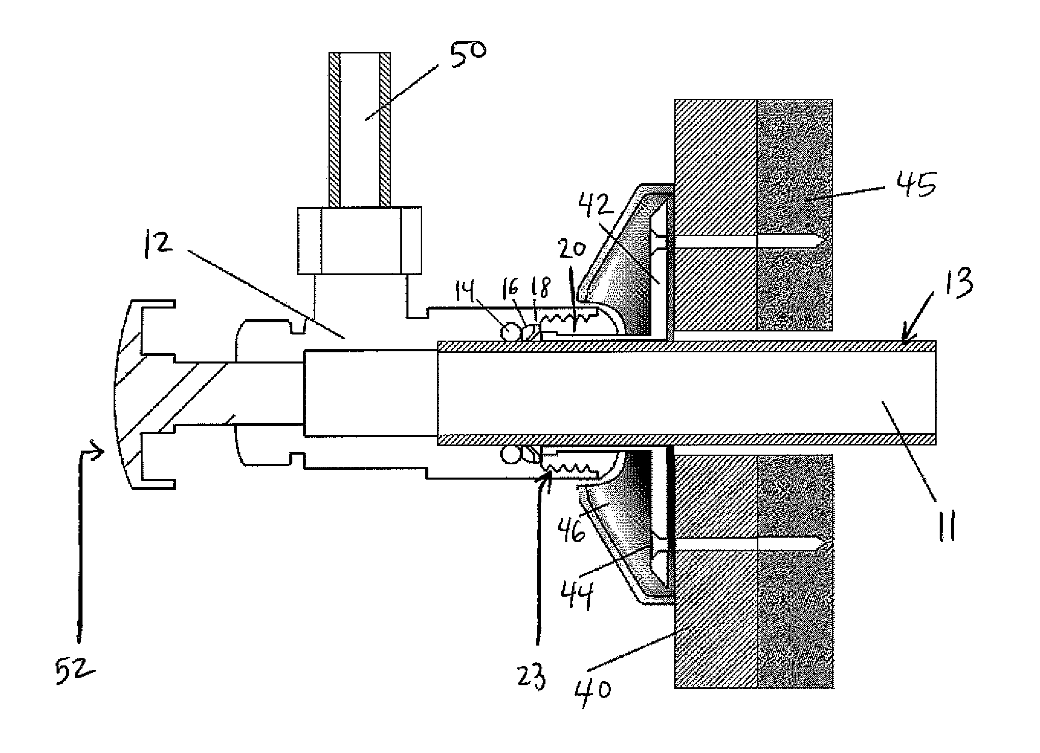
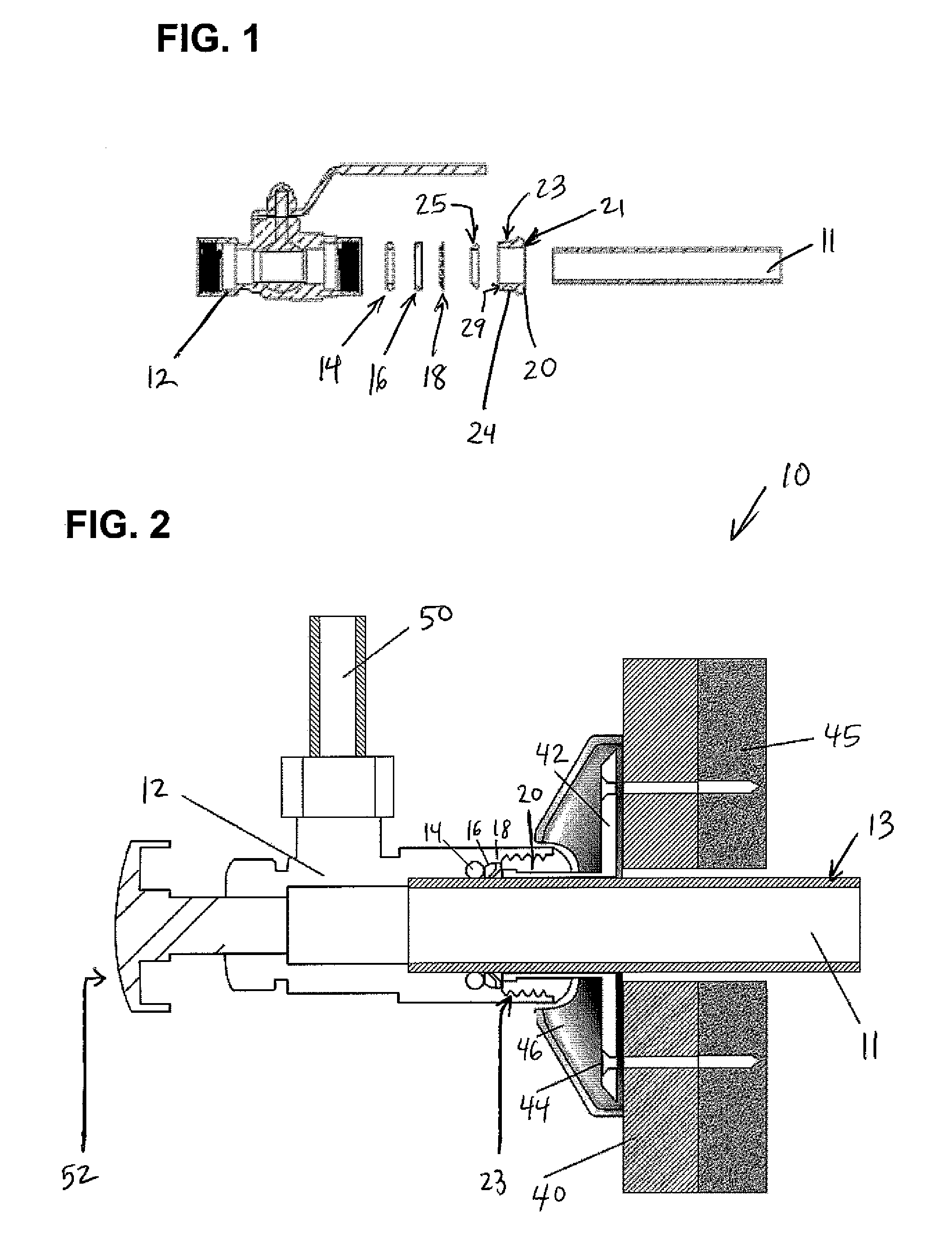
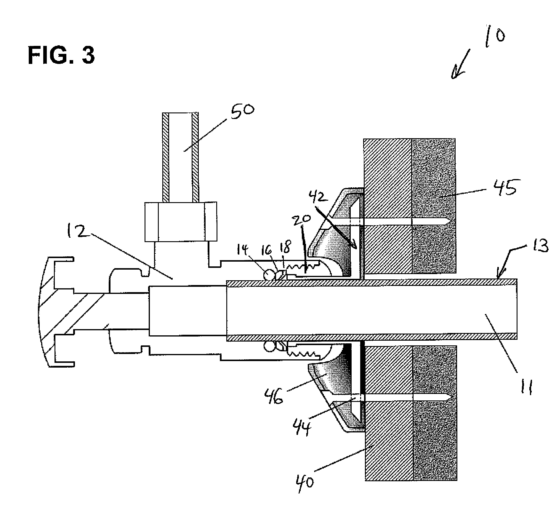
[0020]In the push-fit piping assembly 10 of the present invention as shown in FIGS. 1 through 3, elements of the assembly as shown include: a valve body 12 with interior threads, a male packing gland 16, a fastening or grip ring 18, an O-ring member 14 (which can be optionally lubricated) and a retaining cap 20 (also referred to as a gland nut or packing nut) with exterior threads 23 to mate with the threads on the valve body interior 12. The packing gland 16, fastening ring 18 and O-ring member 14 together provide one embodiment of a packing arrangement for the present invention, and each has an internal diameter that allows for smooth and snug engagement of a pipe 11 and / or fluid supply tubing element external surface 13. A separate pipe 50 is shown extending perpendicularly from pipe 11 in FIGS. 2 and 3. In one embodiment of the present invention, the interior diameter of the packing gland, fastening ring and O-ring member are substantially the same as the interior diameter of th...


PUM


Abstract

The present invention provides an integrated valve, push connection and push release components, and a valve mounting assembly for use on fluid, air or gas applications. The invention allows for the installation of the valve by sliding the valve over the supply tube / piping or pushing the tube / piping into the valve. Once connected, an o-ring seals the connection, a packing gland applies energy to the o-ring seal maintaining constant, even pressure across the seal, and a grip ring applies opposing energy to prevent the disconnection of the assembly. The quick connection assembly is retained by a retaining cap, which applies constant, positive force on the sealing surface.

Description

REFERENCE TO RELATED APPLICATIONS[0001]This application claims the benefit of U.S. provisional patent application Ser. No. 60 / 967,446, filed Sep. 5, 2007 and entitled “Push to Connect Valve, With Integrated Mounting Assembly, Quick Connection Mounting and Quick Dismounting” the disclosure of which is incorporated herein by reference.FIELD OF THE INVENTION[0002]The present invention relates to fluid flow systems, and more particularly to a push-fit valve and integrated mounting assembly that facilitates a push connection and push release of fluid flow valve components while also facilitating repair and re-use of piping system parts.BACKGROUND OF THE PRESENT INVENTION[0003]Piping systems exist to facilitate the flow of fluids (e.g., liquid, gas (such as air) or plasma). For example, homes, schools, medical facilities, commercial buildings and other occupied structures generally require integrated piping systems so that water and / or other fluids can be circulated for a variety of uses....

Claims


Application Information

Patent Timeline
Patent Type & Authority Patents(United States)
IPC IPC(8): F16K27/00
CPCF16L37/091E03C1/042F16L37/0915Y10T137/6977Y10T137/6017Y10T137/6116
Inventor CROMPTON, DAVID B.
Owner QUICK FITTING
Why Eureka
Try Eureka