Incoming material tensioning mechanism of a circular electric plug spot welding device

A technology of spot welding device and electric plug, which is applied in the field of mechanical processing, can solve problems affecting the spot welding process and hindering product production, and achieve the effect of facilitating spot welding and improving work efficiency

Active Publication Date: 2020-03-31
HENAN UNIV OF SCI & TECH
View PDF7 Cites 0 Cited by
  • Summary
  • Abstract
  • Description
  • Claims
  • Application Information

AI Technical Summary

Problems solved by technology

[0002] In some circular electric plugs, the peripheral surface of the circular metal shell part on the outer part should be evenly and standardizedly spot-welded with a circle of strip-shaped metal parts to complete the combination of the two parts, which is a process for the production of finished parts. At present, there is no corresponding ready-made spot welding device for the production of this process, which greatly affects the progress of the spot welding process and seriously hinders the production of products
In view of this situation, the inventor provides a spot welding device for circular electric plugs, which can automatically complete the spot welding of two parts, meet the technological requirements of this process, and make up for the current situation that there is no corresponding spot welding device in the existing production process , because in the process of spot welding, the tension degree of the circular metal shell directly affects the effect of spot welding, so in the spot welding device, the tension of the incoming material for spot welding, that is, the circular metal shell is very important. Important, special tensioning mechanism is required to achieve tensioning of incoming materials

Method used


Image

  • Incoming material tensioning mechanism of a circular electric plug spot welding device
  • Incoming material tensioning mechanism of a circular electric plug spot welding device
  • Incoming material tensioning mechanism of a circular electric plug spot welding device

Examples


Embodiment Construction

[0025] The technical solution of the present invention will be further described through specific implementation manners below in conjunction with the accompanying drawings.

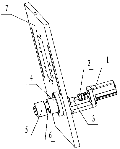
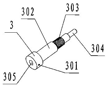
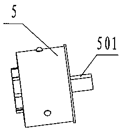
[0026] As shown in the figure, an incoming material tensioning mechanism of a circular electric plug spot welding device includes a tensioning head 5 for tensioning materials, and the tensioning head 5 is fixed on a conductive core driven by a stepping motor 1 to rotate At one end of the shaft 3, the conductive mandrel 3 and a bearing in a bearing seat 4 are installed in cooperation, and the bearing and the conductive mandrel 3 rotate synchronously, and the bearing seat 4 is installed at the through hole position on the support plate 7 of the body, by Screws are fixed, and the stepper motor 1 is fixed on the body support plate 7 by the stepper motor support plate;

[0027] The tensioning head 5 includes a cylindrical outer casing 8, a fastening core 11 and an adjusting screw 12 that are nested with each ...


PUM


Abstract

An incoming material tensioning mechanism of a circular electric plug spot welding device, including a tensioning head for tensioning materials, the tensioning head is connected to one end of a conductive mandrel driven by a stepping motor, and moves along with the conductive mandrel Rotating synchronously, the tensioning head includes a cylindrical outer casing and a fastening core that are nested in each other. Holes are evenly distributed on the side of the outer casing. After the outer casing and the fastening core are sleeved and connected, a The cavity for holding the top tension column, one end of the top tension column and the tension adjustment mechanism on the tension head are installed together, and the tension adjustment mechanism applies different forces to the top tension column, so that the end of the top tension column The top tensioning studs protrude different lengths from the holes on the side of the outer casing to control the tension of the material on the tensioning head. The present invention can tension the incoming material during spot welding and can automatically evenly distribute and rotate the index within 360° of the circumference to facilitate spot welding, and greatly improves the working efficiency of the spot welding device of the circular electric plug.

Description

technical field [0001] The invention belongs to the technical field of mechanical processing, and in particular relates to an incoming material tensioning mechanism of a spot welding device for a circular electric plug. spot welding device. Background technique [0002] In some circular electric plugs, the peripheral surface of the circular metal shell part on the outer part should be uniformly spot-welded with a circle of strip-shaped metal parts to complete the combination of the two parts, which is a process for the production of finished parts. At present, the production of this process does not have a corresponding ready-made spot welding device, which greatly affects the carrying out of the spot welding process and seriously hinders the production of products. In view of this situation, the inventor provides a spot welding device for circular electric plugs, which can automatically complete the spot welding of two parts, meet the technological requirements of this pro...

Claims


Application Information

Patent Timeline
Patent Type & Authority Patents(China)
IPC IPC(8): B23K37/00B23K37/04B23K37/047
CPCB23K37/00B23K37/0443B23K37/047
Inventor 张利平王静鸽尹更新孙红章张帅
Owner HENAN UNIV OF SCI & TECH
Why Eureka
Try Eureka