Injection mold

An injection mold and mold parting technology, applied in the field of plastic product manufacturing, can solve the problems of poor mold ejection effect, low efficiency, and difficulty in ejection of ordinary injection molding machines.

Active Publication Date: 2018-08-10
宁波美丁模塑有限公司
View PDF3 Cites 9 Cited by
  • Summary
  • Abstract
  • Description
  • Claims
  • Application Information

AI Technical Summary

Problems solved by technology

[0002] Plastic products can be seen everywhere in life, and the role of plastic products to human beings is becoming more and more important. There are some problems in the manufacturing process of plastic products. For example, ordinary injection molding machines have difficulties in releasing molds, and some machines cannot realize automatic mold taking, resulting in low efficiency. , and there are certain safety hazards in the working process, and the mold release effect is not good. This device effectively solves this problem

Method used


Image

  • Injection mold
  • Injection mold

Examples


Embodiment Construction

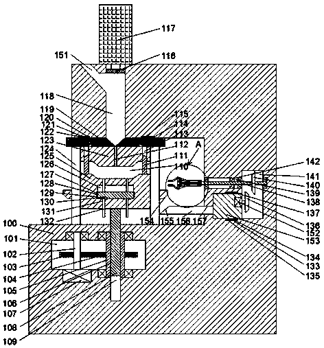
[0020] like Figure 1-Figure 2As shown, an injection mold of the present invention includes a fuselage 100 and a first cavity 110 that is disposed in the fuselage 100 and opens to the left. There is a lower parting mold that can slide up and down in the first cavity 110 125, the lower parting mold 125 is left and right symmetrical and front and rear symmetrically provided with a first through hole that penetrates up and down, and a first sliding rod 124 extending up and down is installed in the first through hole, and the first sliding rod The upper and lower ends of 124 are fixedly connected to the upper and lower end walls of the first cavity 110 respectively, and a first sliding cavity 126 is provided in the lower parting mold 125, and a sliding cavity 126 is provided in the first sliding cavity 126 to slide up and down. The first sliding block 130, the second through hole symmetrically arranged in the left and right sides of the first sliding block 130, the second sliding ...


PUM


Abstract

The invention discloses an injection mold. The injection mold comprises a machine body and a first cavity with a leftward opening, wherein the first cavity is arranged in the machine body; a lower sub-mold capable of sliding up and down is arranged in the first cavity, and first through holes with the upper part communicating with the lower part is formed in the lower sub-mold in a left-right symmetry and front-back symmetry mode, and first sliding rods which extend up and down are installed in the first through holes in a sliding fit mode; and the upper ends and the lower ends of the first sliding rods are fixedly connected to the upper end wall and the lower end wall of the first cavity correspondingly, a first sliding cavity is formed in the lower sub-mold, and a first sliding block isarranged in the first sliding cavity in an up-down sliding mode. According to the injection mold, structure is simple, the problem that mold stripping of the device is difficult is solved through an ejection mechanism, the automatic mold taking of the device is realized by utilizing a clamping device, the working procedures are coordinated with one another and are not affected by one another, labor cost is reduced, and meanwhile, the safety of the device is improved; and the device is automatic in the whole process, operation errors are reduced, the injection molding efficiency and the qualityare improved, and the practical performance of the device is improved.

Description

technical field [0001] The invention relates to the field of plastic product manufacturing, in particular to an injection mold. Background technique [0002] Plastic products can be seen everywhere in life, and the role of plastic products to human beings is becoming more and more important. There are some problems in the manufacturing process of plastic products. For example, ordinary injection molding machines have difficulties in releasing molds, and some machines cannot realize automatic mold taking, resulting in low efficiency. , and there are certain hidden dangers in the working process, and the mold release effect is not good. This device effectively solves this problem. Contents of the invention [0003] The technical problem to be solved by the present invention is to provide an injection mold, which can solve the above-mentioned problems in the prior art. [0004] The present invention is achieved through the following technical solutions: an injection mold of ...

Claims


Application Information

Patent Timeline
Patent Type & Authority Applications(China)
IPC IPC(8): B29C45/53B29C45/66B29C45/42
CPCB29C45/4225B29C45/53B29C45/66
Inventor 张波
Owner 宁波美丁模塑有限公司
Why Eureka
Try Eureka