A kind of pneumatic coating method of charger

A charger and coating technology, which is applied in the field of charger pneumatic coating, can solve the problems of coating offset, skew, heavy labor, etc., and achieve the effect of ensuring the positioning of the coating, accurate positioning and accurate coating

Active Publication Date: 2020-11-24
深せん市奥达电源科技有限公司
View PDF5 Cites 0 Cited by
  • Summary
  • Abstract
  • Description
  • Claims
  • Application Information

AI Technical Summary

Problems solved by technology

With the upgrading of products, some chargers need to cover the six sides (including the pin side and the USB side) with a one-piece protective film. The first corner does not need to be coated, which is the non-coated area. Due to the complex shape of the protective film and the many surfaces of the product that need to be coated, the manual coating method cannot be accurately positioned. It is greatly affected by the level of the operator's coating, and it is very easy The phenomenon that the coating is offset and skewed seriously does not meet the customer's requirements, and the labor load is large and consumes physical strength, which greatly troubles the charger manufacturer.

Method used


Image

  • A kind of pneumatic coating method of charger
  • A kind of pneumatic coating method of charger
  • A kind of pneumatic coating method of charger

Examples


Embodiment Construction

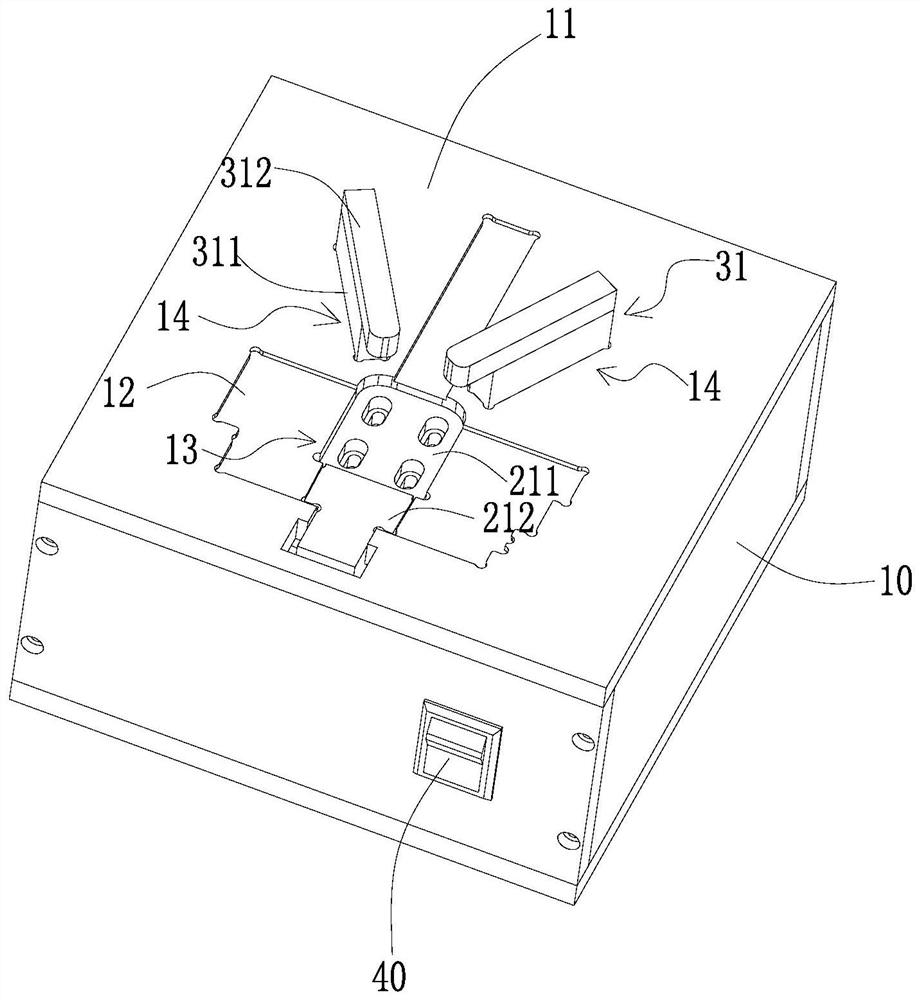
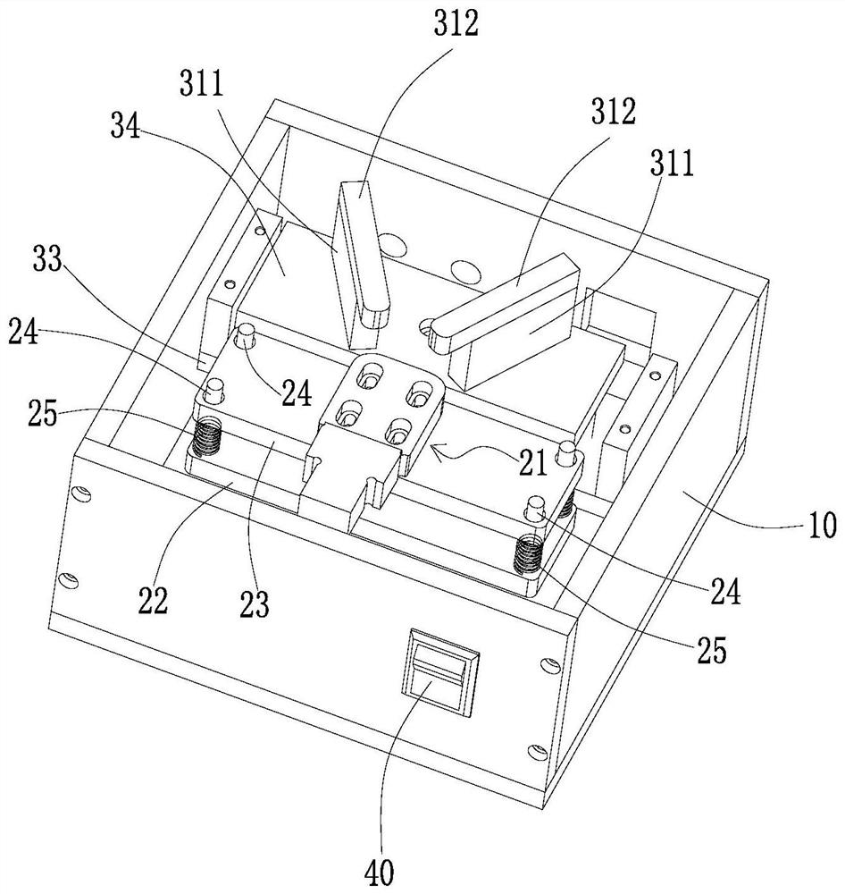
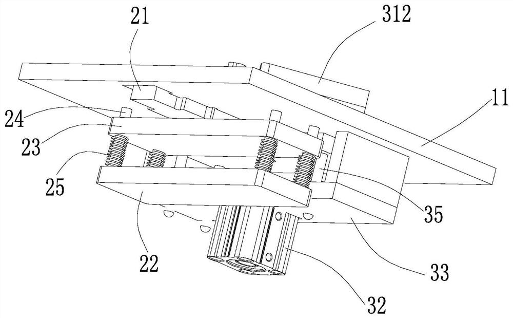
[0027] Such as Figure 1-4 As shown, a charger pneumatic coating jig includes a jig housing 10 , and a charger fixing assembly 20 and a lifting assembly 30 are arranged inside the jig housing 10 . The top cover 11 of the jig housing 10 is provided with a protective film placement groove 12, the protective film placement groove 12 is adapted to be set according to the shape of the protective film used, and the protective film placement groove 12 is provided with an adapter to be coated and charged. tor-shaped first through hole 13

[0028] The charger fixing assembly 20 includes a charger placement table 21 adapted to place a charger to be coated. The charger placement table 21 can be repeatedly pressed down and popped up to be arranged in the first through hole 13, and the initial state (bouncing) When starting) its upper surface is lower than the groove bottom of protective film placement groove 12, conveniently charger is placed accurately. In an embodiment, the charger fi...


PUM


Abstract

The invention discloses a method for pneumatically cover a charger with a film. A pneumatic film covering jig comprises a jig shell. A charger fixing assembly and a lifting assembly are arranged in the jig shell. A protective film storage groove is formed in a top cover of the jig shell. A first through hole is formed in the protective film storage groove. A charger storage table of the charger fixing assembly is liftably arranged in the first through hole. The lifting assembly is provided with a charger pressing component. The method for pneumatically cover the charger with the film comprisesthe following steps that the protective film is positioned and placed in the protective film storage groove with the adhesive surface facing upwards, and the charger to be covered with the film is positioned and placed on the charger storage table; the charger is pressed and fixed by the charger pressing component; and all the surfaces of the charger are covered with the film, then the charger pressing component rises, and the charger is taken out. The method is mainly for chargers with multiple surfaces needing to be covered with protective films in complex shapes, and the protective film and the charger are positioned and placed accuracy and are prevented from floating in the film covering process, so that accurate film covering is ensured, and defects such as deviation and deflection are avoided.

Description

technical field [0001] The invention relates to the field of charger processing, in particular to a charger pneumatic coating method. Background technique [0002] In order to prevent the surface of the finished charger from being scratched, it is necessary to cover the shell of the finished charger with a protective film. In the prior art, the pin surface and the USB surface of most chargers do not need to be covered with a protective film, and the rectangular protective film is artificially covered. After wrapping around the main body of the charger shell, glue the two ends of the protective film. With the upgrading of products, some chargers need to cover the six sides (including the pin side and the USB side) with a one-piece protective film. The first corner does not need to be coated, which is the non-coated area. Due to the complex shape of the protective film and the many surfaces of the product that need to be coated, the manual coating method cannot be accurately ...

Claims


Application Information

Patent Timeline
Patent Type & Authority Patents(China)
IPC IPC(8): B65B33/02
CPCB65B33/02
Inventor 刘昊万泽兵欧阳军郑明星张家栋
Owner 深せん市奥达电源科技有限公司
Why Eureka
Try Eureka