
Rotating pavement paving device

A rotary and rotating shaft technology is applied in the field of rotary road paving devices, which can solve the problems of blockage, low efficiency and inconsistent paving density of paving drive devices, and achieve the effect of low overall cost and improved paving speed.

Inactive Publication Date: 2018-08-10
宗立武
View PDF5 Cites 0 Cited by
  • Summary
  • Abstract
  • Description
  • Claims
  • Application Information

AI Technical Summary

Problems solved by technology

[0003] Paver is a kind of construction equipment mainly used for paving various materials on the base and surface of expressway. However, paver is generally used in large-scale long-distance road construction. Due to the high cost of paver, for some small Most of the paving work on roads and short-distance construction roads is still paved by manpower through shovel pushing, which is very inefficient. Some small paving devices that appear on the market generally use horizontal pushing to pave. , but this way of pushing will lead to problems of inconsistent paving density, clogging of the paving drive or difficulty in advancing the paving device. Therefore, for these problems, we need a small paving suitable for short-distance road paving construction. paving device

Method used


Image

  • Rotating pavement paving device
  • Rotating pavement paving device
  • Rotating pavement paving device

Examples


Embodiment Construction

[0020] The technical solutions in the embodiments of the present invention will be clearly and completely described below in conjunction with the accompanying drawings in the embodiments of the present invention. Obviously, the described embodiments are only a part of the embodiments of the present invention, rather than all the embodiments. Based on the embodiments of the present invention, all other embodiments obtained by those of ordinary skill in the art without creative work shall fall within the protection scope of the present invention.

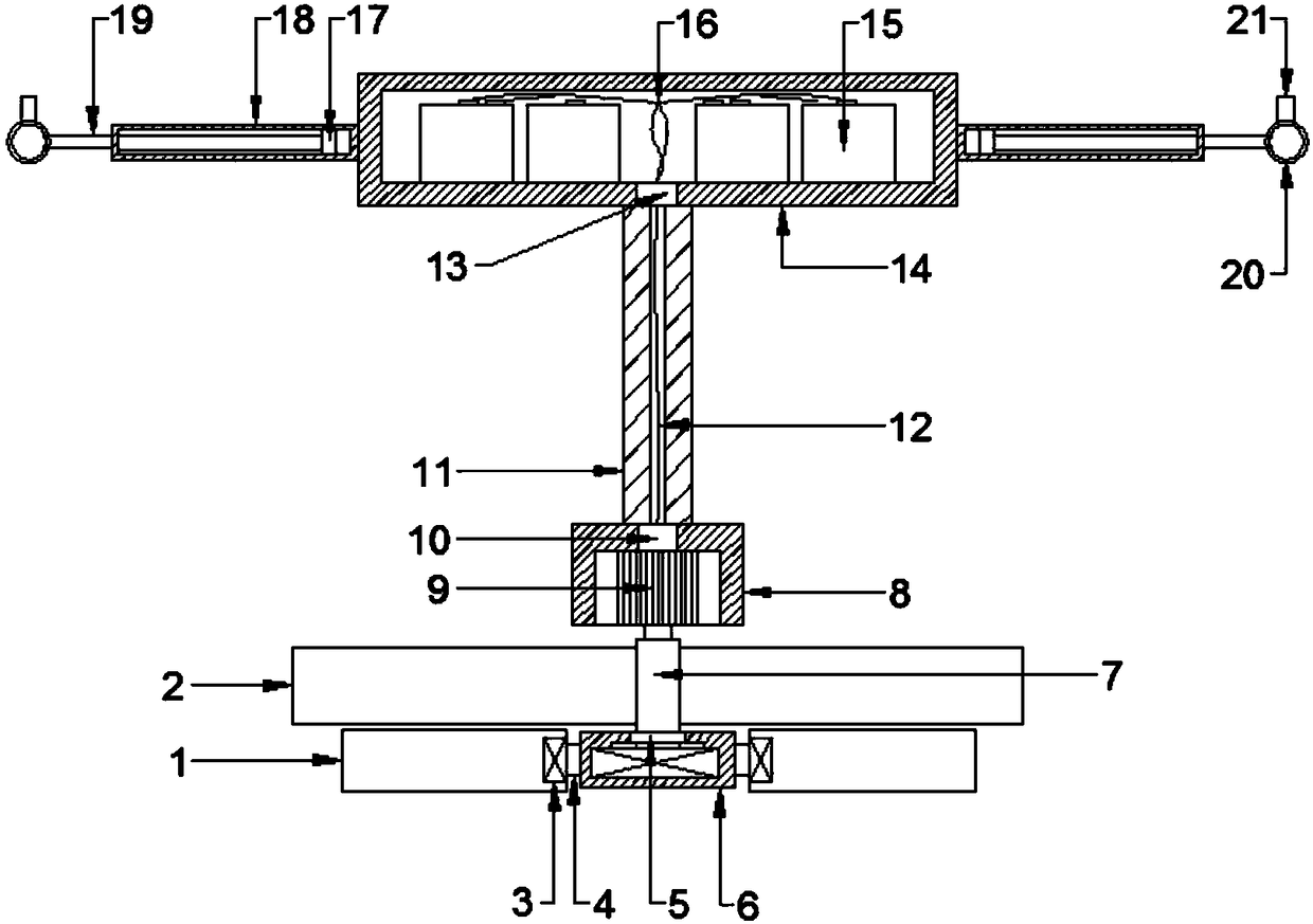
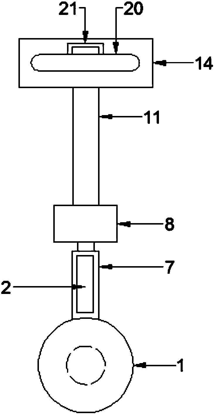
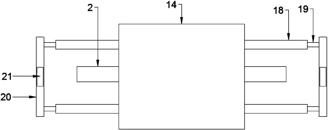
[0021] See Figure 1~4 In the embodiment of the present invention, a rotary road paving device includes a supporting drum 1, a paving scraper 2, a drum bearing 3, a drum shaft 4, a shock-absorbing hole 5, a drum shaft seat 6, a paving shaft 7, Motor mount 8, drive motor 9, cable entry hole 10, support rod 11, threading hole 12, cable outlet hole 13, battery box 14, battery 15, power cord 16, slider 17, sleeve 18, slide rod 19, table The...


PUM


Abstract

The invention discloses a rotating pavement paving device. The rotating pavement paving device comprises a roller rotating shaft seat. Supporting rollers are rotatably fixed on the two side walls of the roller rotating shaft seat. A paving rotating shaft is rotatably fixed to the inner bottom of a base groove of the roller rotating shaft seat. The top end of the paving rotating shaft is fixedly connected with a motor shaft of a driving motor. The driving motor is fixed in the inner wall of a motor fixed seat in an inverted mode. Two symmetrical paving scrapers are fixed on the rod wall of thepaving rotating shaft. The top of a supporting rod is fixed to the center of the bottom surface of a battery box. A plurality of batteries are installed in the battery box. Two sleeve pipes are fixedto the front and back positions of the two side walls of the battery box, and sliding blocks are arranged in the sleeve pipes in a clamped mode. Sliding rods are fixed to the outer end faces of the sliding blocks. The sliding rods penetrate through outer openings of the sleeve pipes. A rack rod is fixed between the front and rear sliding rods, and a push handle is fixed on the top rod wall of therack rod. According to the rotating pavement paving device, the rotating paving scrapers can pave construction materials evenly, so that the paving speed, quality and efficiency of the pavement construction materials are improved.

Description

Technical field [0001] The invention relates to the field of road construction equipment, in particular to a rotary road paving device. Background technique [0002] Pavement paving is mainly to pave the construction materials dumped on the pavement from the piled state when dumping concrete, asphalt and other subgrade construction materials on the pavement, making it a relatively smooth whole, which is convenient for the subsequent construction process. [0003] Paver is a kind of construction equipment mainly used for paving various materials on the base and surface layers of expressways. However, the paver is generally used for large and long-distance pavement construction. Due to the high cost of the paver, it is suitable for some small Pavement and short-distance construction pavement work, most of the paving work is still carried out by manual push through the shovel, and the efficiency is very low. At present, some small paving devices appearing on the market generally use t...

Claims


Application Information

Patent Timeline
Patent Type & Authority Applications(China)
IPC IPC(8): E01C19/12
Inventor 宗立武
Owner 宗立武
Learn More