
Conductive film layer structure, its manufacturing method and touch screen

A technology of conductive film layer and conductive area, applied in the field of touch display, can solve problems such as adverse effects of touch screen, abnormal size, etc.

Active Publication Date: 2021-05-25
ZHANGJIAGANG KANGDE XIN OPTRONICS MATERIAL
View PDF0 Cites 0 Cited by
  • Summary
  • Abstract
  • Description
  • Claims
  • Application Information

AI Technical Summary

Problems solved by technology

[0005] The first purpose of the present invention is to provide a conductive film layer structure. In order to solve the problem of abnormal size due to the expansion and contraction of the screen, the actual position of the laser line directly hitting the conductive area is different from the actual position of the laser line on the CAD drawing. There are deviations, which may cause technical problems that may adversely affect the subsequent use of the manufactured touch screen

Method used


Image

  • Conductive film layer structure, its manufacturing method and touch screen
  • Conductive film layer structure, its manufacturing method and touch screen
  • Conductive film layer structure, its manufacturing method and touch screen

Examples


Embodiment 1

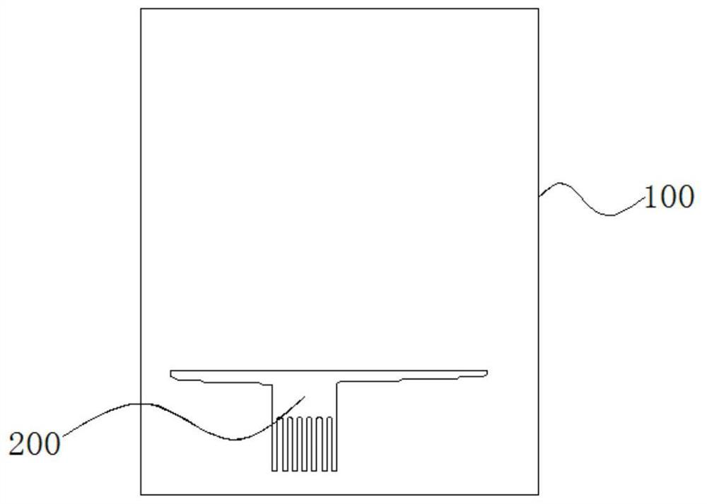
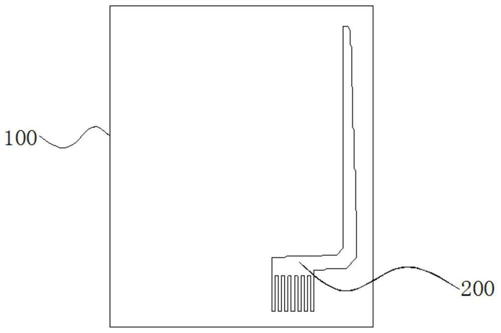
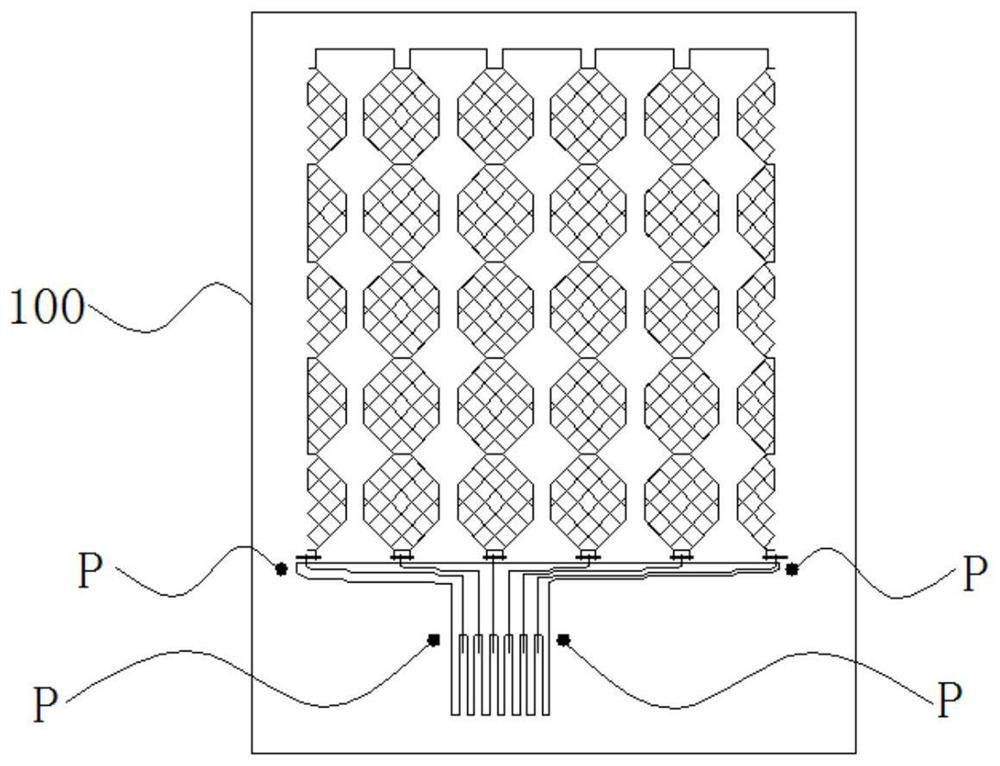
[0048] like Figure 1-4 As shown, the first embodiment provides a conductive film layer structure, including: a conductive film layer 100, the conductive film layer 100 includes a conductive area 200, a sensing area, and a plurality of test blocks for laser line offset adjustment reference A plurality of test blocks are arranged on the outside near the conductive area 200; the test block adopts a structure suitable for the laser line, and the cooperation between the two can facilitate the adjustment of the relative offset between the two.

[0049] In this embodiment, the above-mentioned "conductive material" may use conductive silver paste or be consistent with the material used in the sensing area; when using conductive silver paste, the conductive area 200 may be referred to as a silver paste area.

[0050] In the conductive film layer structure, the conductive film layer 100 is provided with a plurality of test blocks used for laser line offset adjustment references, and th...

Embodiment 2

[0064] The second embodiment provides a method for fabricating the conductive film structure in the first embodiment, including the following steps:

[0065] (A) print conductive area 200 and a plurality of test blocks on the upper or lower film of conductive film layer 100, and print conductive material in conductive area 200;

[0066] (B) Make the laser line hit on a plurality of test blocks, adjust the laser line and align the laser line with each test block;

[0067] (C) Etching the above-mentioned printed conductive material in its entirety.

[0068] It should be noted that, in step (A), the test block and the conductive area 200 are printed at one time by a screen; The position of the block adjusts the offset of the laser relative to the silver paste area as a whole.

[0069] Among them, the method of printing silver paste and laser etching on the upper film is similar to the method of printing silver paste and laser etching on the lower film.

[0070] like image 3 ...

Embodiment 3

[0088] The third embodiment provides a touch screen, including the conductive film layer structure in the first embodiment above.

[0089] Wherein, the conductive film layer structure in the touch screen can be manufactured by the method in the second embodiment.


PUM


Abstract

The invention provides a conductive film layer structure, a manufacturing method thereof and a touch screen, and relates to the technical field of touch display. In order to solve the problem that the actual position of the laser line directly hitting the conductive area is different from the actual position of the conductive area due to the expansion and contraction of the screen plate and the abnormal size. There is a deviation in the actual position of the laser line on the CAD drawing, which may cause technical problems that may adversely affect the subsequent use of the manufactured touch screen. It relates to a conductive film layer structure, comprising: a conductive film layer, the conductive film layer includes a conductive area, a sensing area and a plurality of test blocks used for laser line offset adjustment reference; the plurality of test blocks are respectively arranged near the conductive area The outer side of the test block adopts a structure that is compatible with the laser line, and the cooperation between the two can facilitate the adjustment of the relative offset between the two. The conductive film layer structure, its manufacturing method and the touch screen can adjust the deviation of the laser relative to the silver paste.

Description

technical field [0001] The invention relates to the technical field of touch display, in particular to a conductive film layer structure, a manufacturing method thereof and a touch screen. Background technique [0002] Touch screen, also known as "touch screen" or "touch panel", is an inductive liquid crystal display device that can receive input signals such as contacts. As a new type of computer input device, the touch screen is currently the simplest, most convenient and natural way of human-computer interaction. Today, touch screens are widely used, and their main uses are: corporate meetings, commercial advertisements, education and teaching, intelligent inquiries, exhibitions, smart homes, smart games, etc. [0003] Currently, there are many types of touch screens. Among them, according to the working principle of the touch screen and the classification of the medium for transmitting information, the touch screen can be divided into four types, which are resistive ty...

Claims


Application Information

Patent Timeline
Patent Type & Authority Patents(China)
IPC IPC(8): G06F3/041H05K1/02
CPCG06F3/041G06F3/0412G06F2203/04103H05K1/0266
Inventor 李文李兆勇任小勇
Owner ZHANGJIAGANG KANGDE XIN OPTRONICS MATERIAL
Learn More