Battery pack horizontal button unlocking mechanism and battery pack adopting mechanism

A technology of unlocking mechanism and battery pack, applied in battery pack components, circuits, electrical components, etc., can solve problems such as poor control feel, inability to achieve, and inability to maintain surface contact with inclined plane pairs, and achieve the effect of stable and flexible control

Pending Publication Date: 2018-08-10
NANJING JIUCHI ELECTROMECHANICAL IND
View PDF3 Cites 3 Cited by
  • Summary
  • Abstract
  • Description
  • Claims
  • Application Information

AI Technical Summary

Problems solved by technology

However, this lever button structure is mainly designed to realize the lever swing to automatically push out the battery pack, so the slope pair cannot maintain a stable surface contact during the unlocking process, and the swing displacement of the button has a nonlinear relationship with the lift displacement of the latch. Difference
[0004] In addition, usually the battery pack is "one pack with multiple machines" - that is, it adopts the same up and down drive vertical unlocking structure as the host of various electric tools. The structure needs to change the corresponding adaptation structure of the mainframe at the same time, which is impossible for a large number of mainframes that have entered the market

Method used


Image

  • Battery pack horizontal button unlocking mechanism and battery pack adopting mechanism
  • Battery pack horizontal button unlocking mechanism and battery pack adopting mechanism
  • Battery pack horizontal button unlocking mechanism and battery pack adopting mechanism

Examples


Embodiment 1

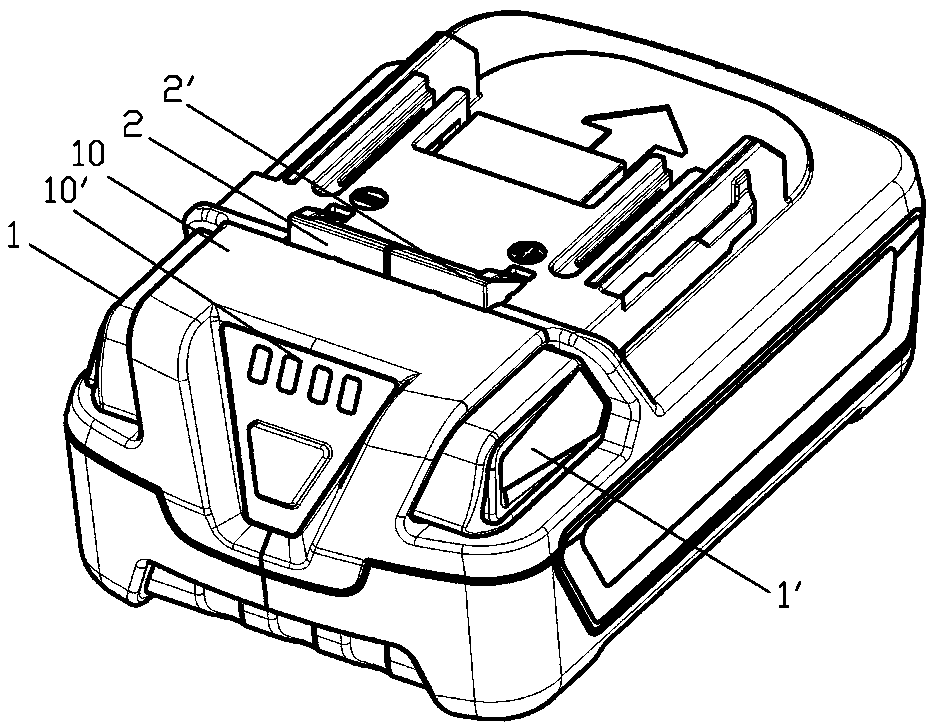
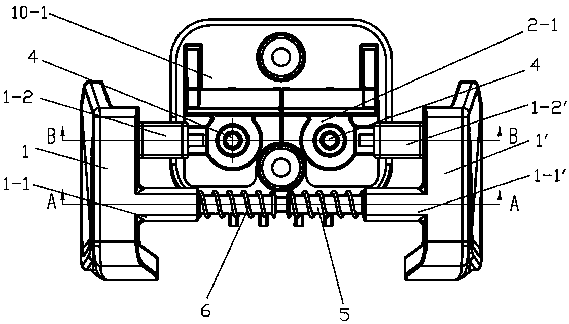
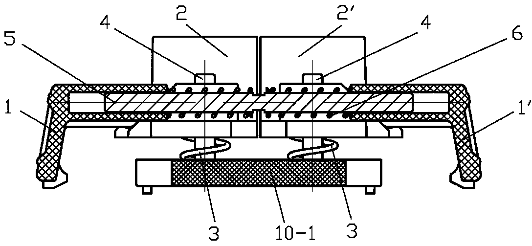
[0029] The battery pack of this embodiment is as figure 1 As shown, the tops of the paired left and right lock buttons 2, 2' that make up the lock bolt protrude from the housing 10, and the cross section of the top is triangular. The bottom of left and right lock button 2,2' is as figure 2 , image 3 and Figure 4 As shown, it is located in the housing 10, and respectively has a boss 2-1 that constitutes a vertical movement pair through the center hole and the left and right guide posts 4. The boss 2-1 has a vertical ring groove for placing the lock button spring 3, the bottom of the guide column 4 is fixed on the base plate 10-1 in the housing 10, and the lower end of the lock button spring 3 is against the base plate of the housing 10 Therefore, the lock bolt composed of the left and right lock buttons 2, 2' tends to rise to the locked position. Stretch out respectively in the both sides hole of housing 10 end and form the left and right unlocking button 1,1 ' of horizo...


PUM


Abstract

The invention relates to a battery pack horizontal button unlocking mechanism, belonging to the technical field of battery power supplying power device. The mechanism comprises a shell in which a battery pack is arranged, a plunger latch with a lower part arranged inside the shell and tending to rise up to lock as well as a left unlocking button and a right unlocking button which stretch out of two sides of the shell, the left unlocking button and the right unlocking button respectively form a horizontal movement pair with the shell, two sides of the plunger latch are respectively in contact with the inner sides of the left unlocking button and the right unlocking button so as to form an inclined plane pair which is used for changing the horizontal displacement of the unlocking button intoa vertical displacement of the plunger latch. During unlocking, the left unlocking button and the right unlocking button are oppositely pinched, and the rising trend of the plunger latch can be overcome through the inclined plane pair which is always in fit to enable the plunger latch to drop and unlock. In the process, the inclined plane pair can always be used for keeping the horizontal displacement of the unlocking button and the lifting displacement of the plunger latch in a linear relation, so that the operation and control are stable and flexible. Especially, by adopting the structure of the invention, the battery pack horizontal button unlocking mechanism can be maintained to adapt to original various main engines, so that the adaptive problem that a battery pack after remodeling is difficult to adapt to a product in the market, is properly solved.

Description

technical field [0001] The invention relates to an unlocking mechanism, in particular to a battery pack horizontal button unlocking mechanism, and also relates to a battery pack using the mechanism, belonging to the technical field of battery-powered power devices. Background technique [0002] Battery-powered power devices such as electric tools are generally equipped with a battery pack that is plugged in by a moving pair and locked in place by a latch mechanism. In the prior art, there are mainly two types of latch mechanisms. The typical structure of the first type is disclosed by the Chinese patent No. ZL200910207248.4. The latch tends to be raised and locked by a vertically operated button to control its descent and unlock; The typical structure of the second category is disclosed in US Patent No. US6168881, in which the latch tends to be extended and locked through a horizontally operated button to control the outward extension to unlock. The former has a simple stru...

Claims


Application Information

Patent Timeline
Patent Type & Authority Applications(China)
IPC IPC(8): H01M2/10B25F5/02H01M50/20
CPCB25F5/02H01M50/20Y02E60/10
Inventor 徐忠鑫
Owner NANJING JIUCHI ELECTROMECHANICAL IND
Why Eureka
Try Eureka