Controlling method of automatic threaded sleeve assembling mechanism

An automatic assembly and control method technology, applied in computer control, program control, general control system, etc., can solve the problems of cumbersome recording of workpiece serial number assembly time, torque, depth, etc., difficult operation, and high labor cost. Achieve real-time information scanning code retrieval query, avoid recording and retrieval, and save labor costs

Active Publication Date: 2020-04-10
CHINA FIRST AUTOMOBILE +1
View PDF8 Cites 2 Cited by
  • Summary
  • Abstract
  • Description
  • Claims
  • Application Information

AI Technical Summary

Problems solved by technology

[0003] 1. When complex parts are assembled with multiple holes, the installation space angle is not easy to control, the labor intensity is high, the efficiency is low, and the threaded sleeve and assembly bottom hole are easily damaged;
[0004] 2. The process torque and depth are controlled by limit and manual, and the fluctuation is large and unstable, so the result can only be monitored;
[0005] 3. During multi-hole assembly, it is easy to miss the assembly of the threaded sleeve and the removal of the tail of the threaded sleeve, and manual deviation may easily cause damage to the workpiece or the threaded sleeve;
[0006] 4. The process parameters need to be manually recorded or input, and the recording of the workpiece serial number, assembly time, torque, depth, etc. is cumbersome and difficult to operate;
[0007] 5. When complex components are assembled with multiple holes, there are many operators and labor costs

Method used


Image

  • Controlling method of automatic threaded sleeve assembling mechanism
  • Controlling method of automatic threaded sleeve assembling mechanism
  • Controlling method of automatic threaded sleeve assembling mechanism

Examples


Embodiment Construction

[0044] The present invention is described in detail below in conjunction with accompanying drawing:

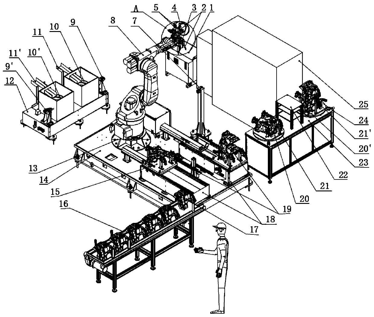
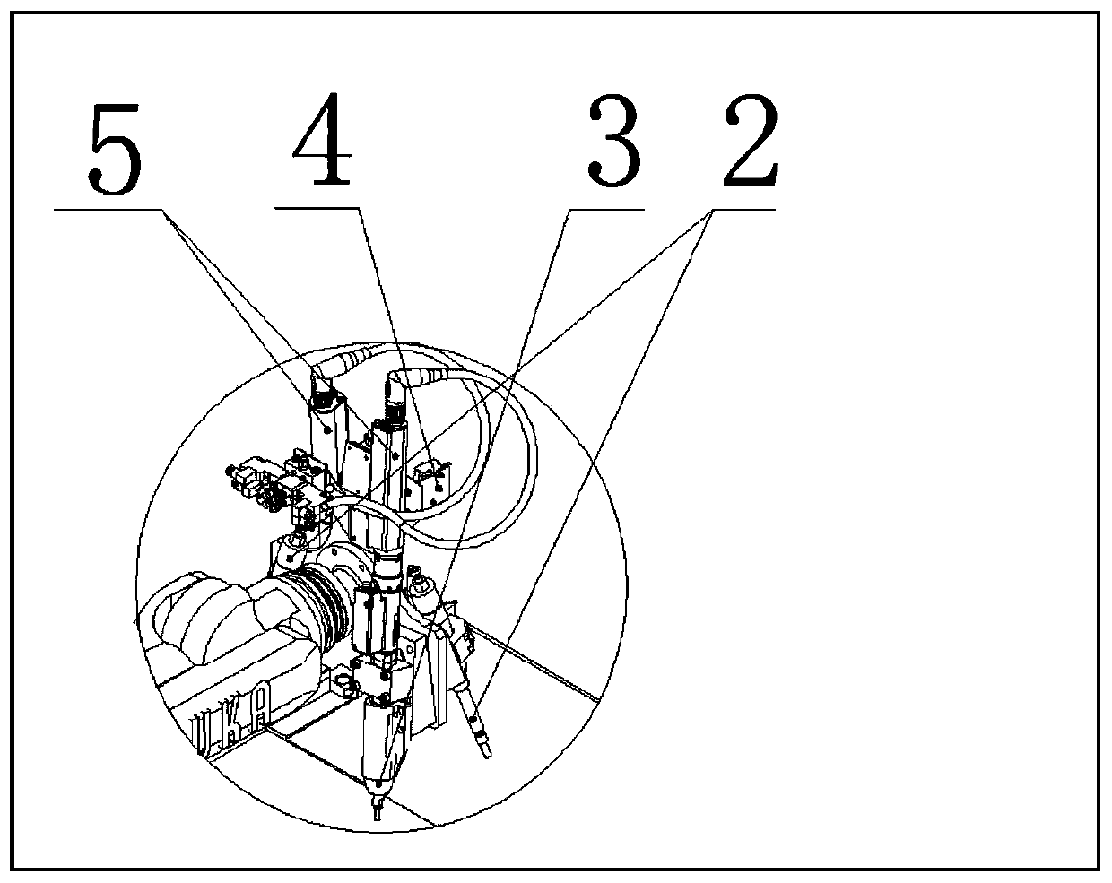
[0045] refer to figure 2 , image 3 , Figure 5 , the whole equipment is mainly composed of feeding slide 18, workpiece positioning fixture 15, hand-held code scanning gun 27, blanking line 16, six-axis robot 8, tail handle punching mechanism 2, threaded sleeve installation mandrel 3, laser sensor 4, thread Sleeve tightening mechanism 5, contact distance sensor 6, threaded sleeve vibration plate 10, threaded sleeve feeding and clamping assembly 12, torque sensor and calibration assembly 7, equipment base assembly 14, control system 25, touch display screen 26, repair work Major components such as Taiwan 23 are formed.

[0046] Through a six-axis robot 8, a threaded sleeve vibration plate 10, a threaded sleeve feeding and clamping assembly 9, a threaded sleeve tightening mechanism 5, a tail handle punching mechanism 2, a laser sensor 4, a contact distance sensor 6, and a fe...


PUM


Abstract

The invention belongs to the technical field of threaded sleeve assembling, and relates to a controlling method of an automatic threaded sleeve assembling mechanism. The controlling method comprises the following steps that 1, a workpiece to be assembled with a threaded sleeve is installed on a workpiece positioning clamp; 2, the threaded sleeve is automatically arranged and fed, and a two-dimensional code of the workpiece is read by an operator holding a code scanning gun; 3, a workpiece positioning clamp is automatically positioned and clamped and positioning detection is carried out, 4, a transfer in-place signal is fed back to a controlling system by a position sensor, and the condition that a current tightening mechanism is calibrated effectively is confirmed by the controlling system; 5, automatic threaded sleeve screwing is carried out, and a threaded sleeve screwing mechanism outputs current hole assembly torque data to the controlling system; 6, a contact type distance sensoris driven to conduct threaded sleeve depth measurement; 7, a tail handle of the threaded sleeve is removed; and 8, a laser sensor is driven to perform tail handle removing confirmation detection. According to the controlling method, high-positioning and repeated-positioning precision including space angles can be achieved, damage to the threaded sleeve and a workpiece assembly bottom hole is avoided, and automatic assembly reduces labor intensity and greatly improves production efficiency.

Description

technical field [0001] The invention belongs to the technical field of threaded sleeve assembly, and relates to a control method for an automatic assembly mechanism of a threaded sleeve. Background technique [0002] At present, it is known that there is no control system for automatic assembly of threaded sleeves including tail removal mechanism in China. Manual assembly or automatic tools with tail removal are used. For mass production, manual assembly with tail removal has disadvantages: [0003] 1. When complex parts are assembled with multiple holes, the installation space angle is not easy to control, the labor intensity is high, the efficiency is low, and the threaded sleeve and assembly bottom hole are easily damaged; [0004] 2. The process torque and depth are controlled by limit and manual, and the fluctuation is large and unstable, so the result can only be monitored; [0005] 3. During multi-hole assembly, it is easy to miss the assembly of the threaded sleeve ...

Claims


Application Information

Patent Timeline
Patent Type & Authority Applications(China)
IPC IPC(8): B23P19/04G05B19/4155
CPCB23P19/001B23P19/004B23P19/04G05B19/4155
Inventor 赵建锋张云峰张倩王晓秋王甫峰
Owner CHINA FIRST AUTOMOBILE
Why Eureka
Try Eureka