Sandwich metal plate

A metal sheet and sandwich technology, applied in the direction of metal layered products, sheets/plates, building elements, etc., can solve the problems of not pointing out the formation of through air passages, uneven heating, and not raising heating, etc. Welding efficiency, good welding effect, and the effect of improving brazing quality

Active Publication Date: 2018-08-14
张跃
View PDF8 Cites 17 Cited by
  • Summary
  • Abstract
  • Description
  • Claims
  • Application Information

AI Technical Summary

Problems solved by technology

This structure is that the corrugated brazing sheets are stacked or wound, and the assembly is brazed in an inert gas atmosphere at the brazing temperature, but the high temperature gas is not used for circulation heating in the inner cavity of the workpiece, which still causes lead to uneven heating
[0005] The existing sandwich composite panels also have a structure in which the core tubes are arranged at intervals, but it is not pointed out that the air passage is formed through, and it is not proposed to combine the brazing process with the workpiece structure to circulate and heat the inner cavity of the workpiece to solve the problem of uneven heating. technical problem

Method used


Image

  • Sandwich metal plate
  • Sandwich metal plate
  • Sandwich metal plate

Examples


Embodiment 1

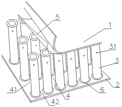
[0031] Such as figure 1Shown: a sandwich metal sheet, including an upper panel 1, a lower panel 2, and several core tubes 3 between the upper panel 1 and the lower panel 2; a plurality of core tubes 3 are provided with through air passages 4, Between the core tube 3 and the upper panel 1 and the lower panel 2, high-temperature gas is used to flow back and forth and left and right through the air channel 4 to realize brazing.

[0032] Specifically, the core tube 3 is a round tube, and the number of core tubes can be selected according to needs. Adjacent core tubes 3 are arranged at intervals to form transverse air passages 41 and longitudinal air passages 42, wherein the row spacing between the core tubes 3 is 40 mm, and the column spacing is 70 mm. The high-temperature gas enters the inner cavity of the sandwich metal plate through the transverse air channel 41 and the longitudinal air channel 42 . Wherein, the core tube 3, the upper panel 1, and the lower panel 2 are brazed...

Embodiment 2

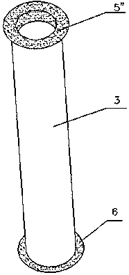
[0037] Such as figure 2 Shown: the difference with embodiment 1 is that the upper and lower ends of the core tube 3 are punched and flanged 6; The material is copper solder 5", and the copper solder 5" is set between the flange 6 of the core tube 3 and the upper and lower panels in the form of a foil sleeve, that is, the copper solder 5" wraps the flange of the core tube 3 6, and extend into the core tube 3, so that the core tube 3 is covered, so that the core tube 3 can be firmly positioned between the panels.

[0038] Others are with embodiment 1.

Embodiment 3

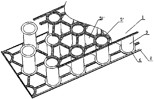
[0040] Such as image 3 Shown: The difference from Example 2 is that the copper solder 5' is arranged between the flange 6 of the core tube 3 and the upper panel 1 and the lower panel 2 in the form of a foil sleeve, and the copper solder 5' is not covered The position of the core tube is provided with a hollow 51 ′, such as a triangular hollow, which can prevent excess copper solder 5 ′ from accumulating during the brazing process and greatly improve the brazing quality.

[0041] Others are with embodiment 2.


PUM

PropertyMeasurementUnit
thicknessaaaaaaaaaa

Abstract

The invention relates to a sandwich metal plate. The sandwich metal plate comprises an upper panel, a lower panel and a plurality of core tubes, wherein the multiple core tubes are arranged between the upper panel and the lower panel, penetrating air passages are arranged among the multiple core tubes, and the core tubes as well as the upper panel and the lower panel are brazed through fore-and-aft and / or left-and-right circulating heating by utilizing high-temperature gas through the air passages. On one hand, the sandwich metal plate has the advantages of light weight, high strength, heat insulation and the like, and on the other hand, the sandwich metal plate cannot be deformed by heat difference, so that the permanent service life of the sandwich metal plate is guaranteed.

Description

technical field [0001] The invention relates to the technical field of composite materials, in particular to a sandwich metal plate. Background technique [0002] Most of the existing sandwich composite panels are made of honeycomb sandwich panels. The honeycomb cores are usually arranged closely together and brazed by radiation heating. This heating method is slow, which easily leads to uneven heating of the workpiece, resulting in heat generation. Deformation greatly increases the rate of defective products, reduces service life, and increases production costs; and after heating, the workpiece needs to be transported to the cooling chamber for cooling. Heating and cooling cannot be completed at one time, which greatly increases the working time and reduces efficiency. [0003] For example, CN100560350C discloses a metal honeycomb sandwich combined energy-absorbing structural material, the energy-absorbing material includes a shell, a metal honeycomb sandwich body combinati...

Claims


Application Information

Patent Timeline
Patent Type & Authority Applications(China)
IPC IPC(8): F16S1/04B32B3/08B32B15/01B32B15/18
CPCB32B3/085B32B15/011B32B2307/304B32B2307/558B32B2307/718F16S1/04
Inventor 张跃
Owner 张跃
Why Eureka
Try Eureka