antenna system

An antenna system and antenna unit technology, applied in the field of mobile communications, can solve the problems of simultaneous coverage of radiation units of a single branch, small headroom, limited space, etc., to reduce the required space, reduce the required space of the antenna, increase the Effect of Antenna Broadband

Active Publication Date: 2020-12-22
AAC TECH PTE LTD
View PDF17 Cites 0 Cited by
  • Summary
  • Abstract
  • Description
  • Claims
  • Application Information

AI Technical Summary

Problems solved by technology

[0004] For example, in the existing GPS / WIFI antenna, the working frequency band of the GPS antenna is 1550-1650MHz, and the working frequency band of the WIFI2.4G antenna is 2400-2500GHz. Small), it is difficult to cover the GPS / WIFI2.4G frequency band at the same time through a single radiation unit

Method used


Image

  • antenna system
  • antenna system
  • antenna system

Examples


Embodiment 1

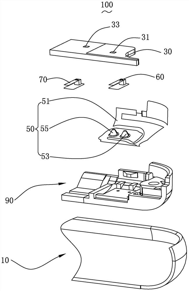
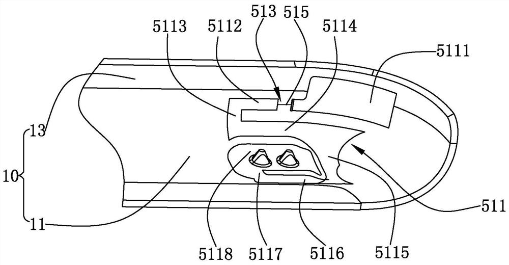
[0025] Please also see figure 1 and figure 2 ,in, figure 1 is an exploded schematic view of the antenna system of the present invention, figure 2 for figure 1 A schematic diagram of the connection structure of the housing and the antenna unit in the antenna system shown. The present invention provides an antenna system 100, which is applied to a mobile terminal. The antenna system 100 includes a casing 10 , an antenna unit 50 , a circuit board 30 accommodated in the casing 10 , a feed pin 60 , a ground pin 70 and a plastic bracket 90 . The mobile electronic device may be a mobile phone, a handheld game device, a notebook computer, a music player, and the like.

[0026] The casing 10 includes a bottom plate 11 spaced apart from the circuit board 30 and a side plate 13 extending from the bottom plate 11 toward the circuit board 30 . The connection between the bottom plate 11 and the side plate 13 is an arc surface.

[0027] In this embodiment, the housing 10 is a non-me...

Embodiment 2

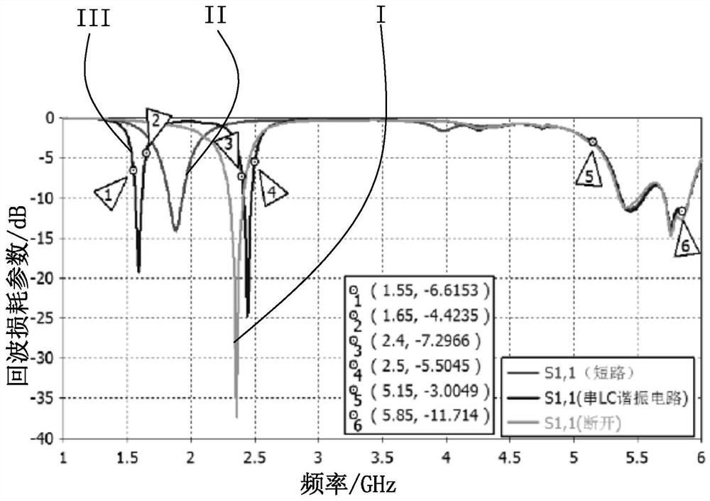
[0055] In this embodiment, the antenna system includes a housing, an antenna unit and a circuit board accommodated in the housing. The housing includes a metal frame that acts as a radiation body, and the gap is opened in the metal frame. It is also an LC parallel resonant circuit composed of an LC parallel circuit connected in series in the gap. The principle of adjusting the frequency band is the same as that described above. This will not be repeated here.

[0056] It should be noted that the present invention does not limit the operating frequency band of the antenna system, that is, it can be applied to GPS / Wi-Fi antenna modules, and can also be used in other antenna modules, such as main antenna and diversity antenna.

[0057] In addition, the present invention does not limit the implementation of the LC parallel resonant circuit. For example, a parallel circuit with a fixed value can be bridged by discrete inductance elements and capacitance elements, and a tunable par...


PUM


Abstract

The invention provides an antenna system. The antenna system comprises a housing, an antenna unit, and a circuit board accommodated in the housing. The circuit board comprises a feeder part and a grounding part. The antenna unit comprises a radiation body, a feeder terminal, and a grounding terminal. The two ends of the feeder terminal are electrically connected with the radiation body and the feeder part. The two ends of the grounding terminal are electrically connected with the radiation bod and the grounding part. The antenna system is characterized in that the radiation body comprises aradiation main body, a slit formed by the fracture of the radiation main body, and an LC parallel connection resonance circuit serially connected with the inner side of the slit, and the LC parallel connection resonance circuit comprises a capacitor and an inductor, which are parallely connected together. Compared with the prior art, by using the impedance characteristic of the LC parallel connection resonance circuit, the requirement of the antenna on different frequency bands can be satisfied, and space required by the antenna is effectively reduced, and a design requirement on more MIMO antennas is facilitated.

Description

【Technical field】 [0001] The invention relates to the field of mobile communication, in particular to an antenna system applied to a mobile terminal. 【Background technique】 [0002] With the advent of the mobile Internet era, portable mobile electronic devices have become increasingly popular. Among the many mobile devices, the mobile phone is undoubtedly the most common and portable mobile terminal device. As people continue to pursue the speed of Internet access, it is imperative to increase the data transmission rate of mobile phones, and MIMO (Multiple-Input Multiple-Output) technology has also been widely used. MIMO technology can significantly increase the channel capacity without expanding the bandwidth of the communication frequency band, thereby increasing the data transmission rate. In addition to the main antenna and the diversity antenna, the flagship mobile phone antennas of many mobile phone manufacturers on the market have added at least two additional MIMO ...

Claims


Application Information

Patent Timeline
Patent Type & Authority Patents(China)
IPC IPC(8): H01Q1/24H01Q21/00H01Q23/00
CPCH01Q1/242H01Q21/00H01Q23/00
Inventor 韩洪娟刘见传岳月华
Owner AAC TECH PTE LTD
Why Eureka
Try Eureka