Iris collecting device and method for controlling turn-on time of infrared lamp

A technology of iris collection and infrared lamps, which is applied to color TV parts, TV system parts, TVs, etc., can solve the problems of low current intensity of lighting units, degradation of iris imaging quality, and reduced user experience effects, so as to avoid The effect of lens reflection, alleviating equipment heat dissipation, and overcoming bad frame phenomenon

Active Publication Date: 2018-08-14
BEIJING IRISKING
View PDF10 Cites 17 Cited by
  • Summary
  • Abstract
  • Description
  • Claims
  • Application Information

AI Technical Summary

Problems solved by technology

[0002] The lighting mode of the traditional iris collection device is a continuous lighting scheme or a fixed frequency pulse lighting scheme. The current intensity of the lighting unit is low, and the image sensor needs a certain integration time to accumulate charges to collect iris images that meet the brightness requirements, which is easy to cause motion blur. , so that the imaging definition is poor, which cannot meet the application scenario of iris recognition during the user's mobile process, and reduces the user experience effect
[0003] In addition, on the iris recognition equipment with two sets of left and right infrared light sources, the left and right infrared light source cross lighting scheme is usually used to reduce the reflection problem of the lens. The traditional lighting scheme of driving the infrared light source with a fixed frequency pulse has certain disadvantages, which is easy to cause bad frames.
The reason is that the illumination timing of the left and right infrared light sources is difficult to keep in sync with the exposure time of each frame of image by the image sensor, resulting in the lack of uniform infrared illumination within the exposure time of the corresponding image frame when the left and right light sources alternate, resulting in dark stripes in the imaging , leading to a decrease in iris imaging quality

Method used


Image

  • Iris collecting device and method for controlling turn-on time of infrared lamp
  • Iris collecting device and method for controlling turn-on time of infrared lamp
  • Iris collecting device and method for controlling turn-on time of infrared lamp

Examples


Embodiment 1

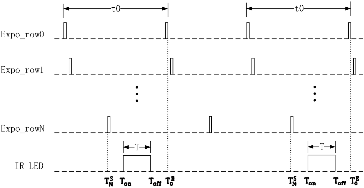
[0049] Under the condition that the turn-on time of the infrared lamp satisfies the formula (1), the motion blur in the imaging can be greatly reduced.

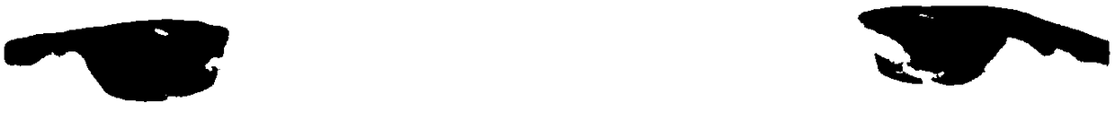
[0050] Figure 3a1 ~ Figure 3b4 Shown is the schematic diagram of the image collected by the iris collection device of the first embodiment of the present invention, and the iris sequence of the iris collection device is approached from far and near. Figures 3a1-3a3 Motion blur is noticeable until the tester arrives Figure 3a4 When the corresponding position stops moving, the image becomes clear; Fig. 3b is an image collected by the method for calculating the time of turning on the infrared lamp according to the present invention, Figures 3b1-3b4 Both are relatively clear, motion blur is significantly reduced, and iris texture clarity is effectively enhanced.

Embodiment 2

[0052] Under the condition that the turn-on time of the infrared lamp satisfies the formula (1), the heat dissipation effect of the infrared lamp can be improved.

[0053] Figure 4 Shown is the comparison chart of the infrared lamp turn-on mode of the iris collection device of the present invention and the traditional infrared lamp turn-on mode, as Figure 4 As shown, 1: indicates the rolling exposure mode of the image sensor; 2: indicates the constant-on mode of the infrared light; 3: indicates the pulse-on mode of the infrared light; 4: indicates the turning-on mode of the infrared light of the present invention.

[0054] There is a certain interval between the charge integration time of the image sensor for each frame of image, that is, the blank time. The traditional always-on light-on mode is adopted, and the light is continuously illuminated during the integration time of the image sensor and the blank time, resulting in the blank time. Waste of resources; the use of t...

Embodiment 3

[0071] Under the condition that the turn-on time of the infrared lamp satisfies the formula (1), the left and right groups of infrared lamps can be illuminated alternately in a real sense, and the bad frame phenomenon that occurs in the fixed-frequency pulse lighting method can be avoided.

[0072] Wherein, the scheme of alternating lighting of infrared lamps is to set a group of infrared lamps on the left and right sides of the camera module of the iris collection device, and control the two groups of infrared lamps on the left and right to alternately illuminate. The traditional alternative lighting scheme of infrared lamps is infrared The light is turned on and off at a fixed frequency, which may easily cause bright and dark stripes in the captured image;

[0073] The present invention is based on Figure 5 The shown method of turning on the infrared lamp calculates the time sequence according to the method of calculating the turning on time of the infrared lamp, that is, t...


PUM


Abstract

The invention discloses an iris collecting device for controlling turn-on time of an infrared lamp. The device comprises an image sensor, a camera module, an infrared lamp, a micro control unit; the micro control unit detects a frame synchronization signal sent by the image sensor and computes exposure time of the image sensor, computes the turn-on time of the infrared lamp, and controls the on-ffof the infrared lamp. Through the iris collecting device disclosed by the inventio, the infrared lamp power consumption can be reduced, and the motion blurring is eliminated; the bad frame phenomenoncan be avoided in an alternate lighting scheme, thereby guaranteeing that each frame image can acquired exposure with uniform brightness.

Description

technical field [0001] The invention relates to the field of image acquisition, in particular to an iris acquisition device and method for controlling the turn-on time of an infrared lamp. Background technique [0002] The lighting mode of the traditional iris collection device is a continuous lighting scheme or a fixed frequency pulse lighting scheme. The current intensity of the lighting unit is low, and the image sensor needs a certain integration time to accumulate charges to collect iris images that meet the brightness requirements, which is easy to cause motion blur. , so that the imaging definition is poor, which cannot meet the application scenario of iris recognition during the user's movement, and reduces the user experience effect. [0003] In addition, on the iris recognition equipment with two sets of left and right infrared light sources, the left and right infrared light source cross lighting scheme is usually used to reduce the reflection problem of the lens....

Claims


Application Information

Patent Timeline
Patent Type & Authority Applications(China)
IPC IPC(8): H04N5/235H04N5/374G06K9/00
CPCG06V40/19H04N23/74H04N25/76
Inventor 何召锋邱显超李言王琨李星光
Owner BEIJING IRISKING
Why Eureka
Try Eureka