

Elbow-shaped longitudinal beam and space extension arm
An extension arm and elbow-shaped technology, which is applied in the field of satellite structures, can solve problems such as the implementation of elbow-shaped longitudinal beams and leaf spring structures that are not specifically introduced, and achieve the effects of facilitating installation and use, large expansion and contraction ratio, and good thermal stability
Active Publication Date: 2014-05-28
XIAN INSTITUE OF SPACE RADIO TECH
View PDF0 Cites 2 Cited by
- Summary
- Abstract
- Description
- Claims
- Application Information
AI Technical Summary
Problems solved by technology
New York: John Wiley & Sons Inc., 1997 introduced the principle of the space extension arm, but did not specifically introduce the specific structural realization of the elbow longitudinal beam and the leaf spring
Method used
View moreImage
Smart ImageViewing Examples

Examples
Embodiment Construction
Login to View More PUM
 Abstract
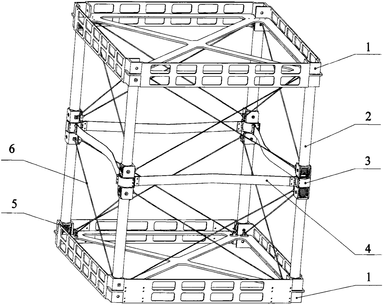
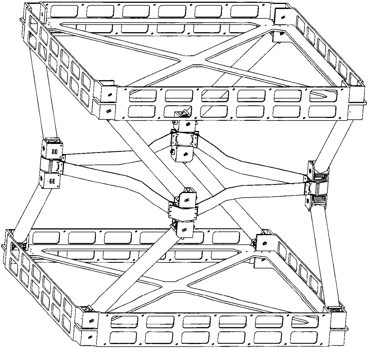
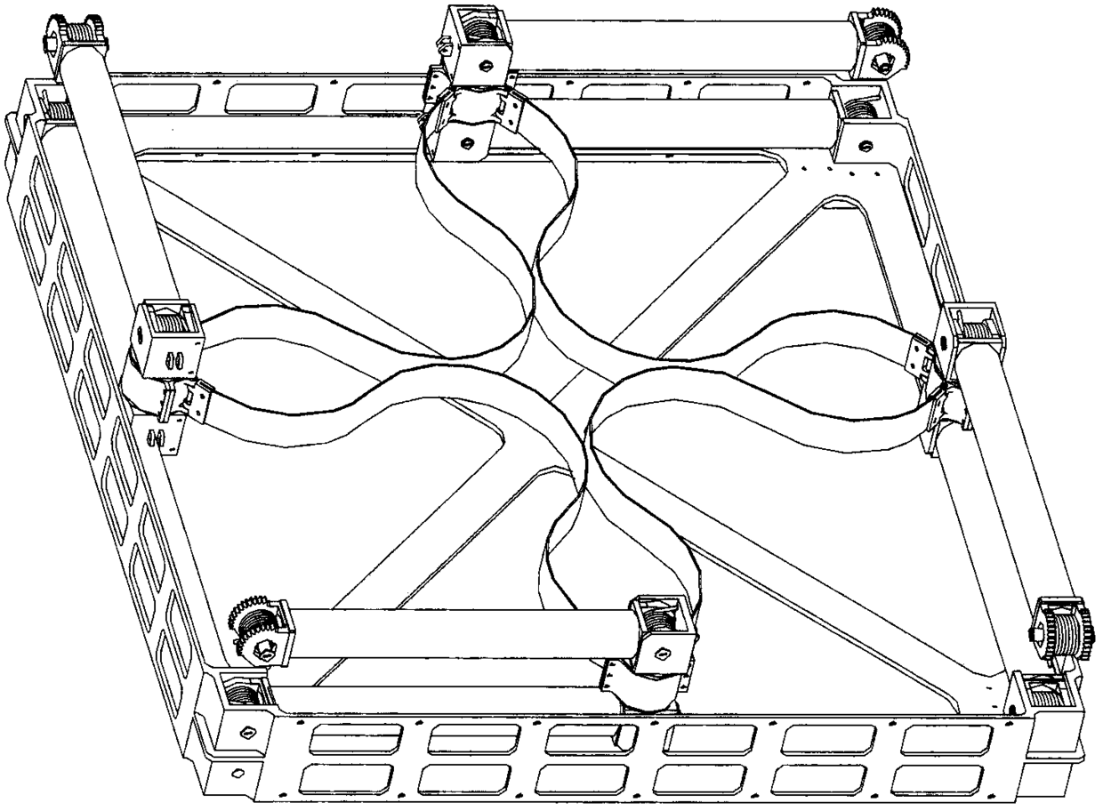
An elbow-shaped longitudinal beam and a space extension arm. The elbow-shaped longitudinal beam is divided into left and right parts with the elbow as the center. The two parts share a middle hinge box, and each part includes a carbon fiber tube, an elbow joint torsion spring, and a rolling bearing. , synchronous gear, sliding bearing, shaft 1, toothed joint 1, shaft 2, guide rod and toothed joint 2; the left and right parts are meshed by synchronous gears; the synchronous gears of each part are installed in the middle of the middle hinge box through shaft 1 Sliding bearings are installed between the shaft one and the synchronous gear; the toothed joint one is installed on both sides of the middle hinge box through the shaft two, and meshes with the above synchronous gears, and the rolling bearing is installed between the toothed joint one and the second shaft; the toothed joint One is connected to one end of the carbon fiber tube, and the other end of the carbon fiber tube is connected to the tooth joint two; the elbow joint torsion spring is installed on the shaft two through the guide rod, and one torsion arm of the elbow joint torsion spring is limited by the middle hinge box, and the other A torsion arm is limited by a toothed joint.
Description
technical field The invention relates to a novel elbow-shaped longitudinal beam and a space extending arm, belonging to the field of satellite structures. Background technique In China, some achievements have been achieved in the research of sleeve rods, disc pressure rods and stay cable locking rods (also called cable-rod stretching arms). When the antenna unit is fixed in multiple directions, the above-mentioned extension arms can only install the antenna at the top of the extension arm due to the limitation of rigidity or folding method, which cannot meet the requirement of fixing the antenna unit in the middle of the extension arm. At present, there is no report on the content of this technology in China. Chen Liemin. Spacecraft Structure and Mechanism. Beijing: China Science and Technology Press, 2005, only briefly introduced the concept and principle of the extension arm, and did not introduce the specific structure details. Foreign literature Conley P L. Space Vehic...
Claims
Login to View More Application Information
Patent Timeline
 Patent Type & AuthorityPatents(China)
IPC IPC(8): B64G1/66B64G1/22
Inventor王锋斌史明杨俊良周丽萍
OwnerXIAN INSTITUE OF SPACE RADIO TECH