System and method for preventing excessive flying shear tail

A flying shear, oversized technology, applied in the field of steel rolling, can solve the problem of oversized cutting tail, and achieve the effect of avoiding flying shears from being stuck, preventing flying shearing tails from being oversized, reducing push waste and abnormal shutdown.

Active Publication Date: 2019-09-20
SHOUGANG JINGTANG IRON & STEEL CO LTD
View PDF7 Cites 0 Cited by
  • Summary
  • Abstract
  • Description
  • Claims
  • Application Information

AI Technical Summary

Problems solved by technology

[0003] The present invention solves the technical problem of excessive cutting tail caused by the interference of oxide scale at the tail of the intermediate billet in the prior art by providing a system and method for preventing the flying shear tail from being too large

Method used


Image

  • System and method for preventing excessive flying shear tail
  • System and method for preventing excessive flying shear tail
  • System and method for preventing excessive flying shear tail

Examples


Embodiment 1

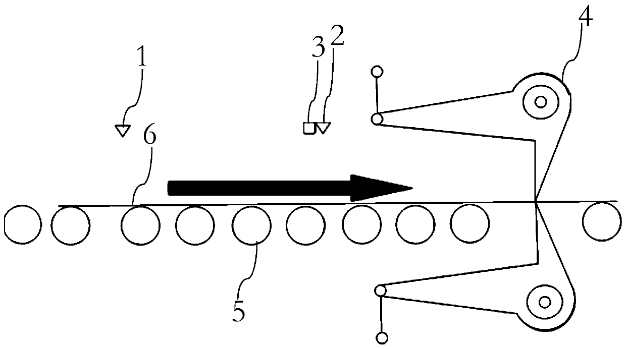
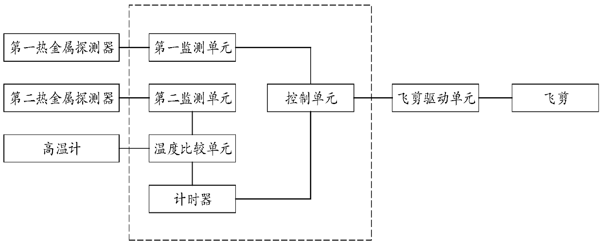
[0036] see figure 1 , the present embodiment provides a system for preventing the flying shear tail from being too large, and the system includes: a roller table 5, a first hot metal detector 1, a second hot metal detector 2, a pyrometer 3, and a flying shear driving unit , flying shear 4 and controller. The first hot metal detector 1, the second hot metal detector 2 and the pyrometer 3 are arranged above the roller table 5; the second hot metal detector 2 and the pyrometer 3 are arranged on the downstream of the first hot metal detector 1, This downstream refers to the downstream of strip steel 6 running direction, figure 1 The direction indicated by the middle arrow is the running direction of strip 6. The irradiation points of the second hot metal detector 2 and the pyrometer 3 on the steel strip 6 are set at the same position, and the measuring range of the pyrometer 3 is 600-1200°C. The flying shear driving unit is connected with the flying shear 4, and drives the flyi...

Embodiment 2

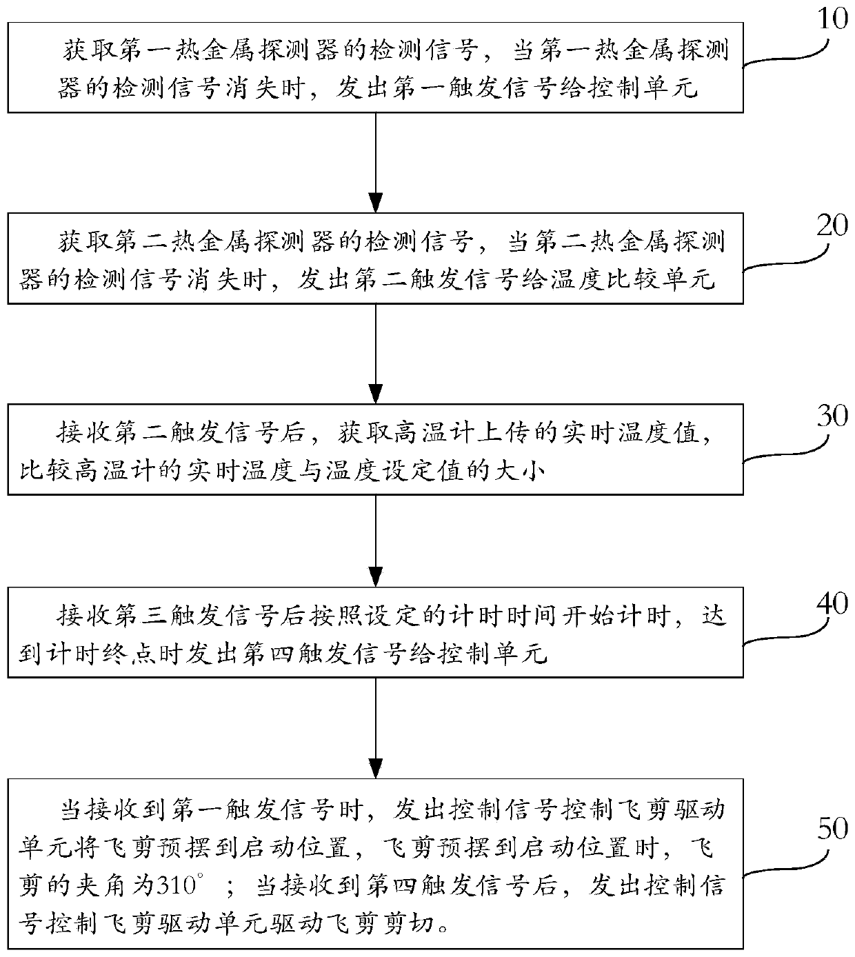
[0044] see figure 1 and image 3 , present embodiment provides a kind of method that prevents flying shear tail from being too large, and this method is that strip steel 6 realizes after running on roller table 5, comprises the following steps:

[0045] Step 10, acquiring the detection signal of the first hot metal detector 1, and sending a first trigger signal to the control unit when the detection signal of the first hot metal detector 1 disappears.

[0046] Step 20, acquiring the detection signal of the second hot metal detector 2, and sending a second trigger signal to the temperature comparison unit when the detection signal of the second hot metal detector 2 disappears.

[0047] Step 30, after receiving the second trigger signal, obtain the real-time temperature value uploaded by the pyrometer 3, and compare the real-time temperature of the pyrometer 3 with the temperature setting value. In this embodiment, the temperature setting value is 700°C. If the real-time temp...


PUM


Abstract

The invention relates to the technical field of rolled steel, in particular to a system for preventing a flying shear back-end crop from being too big. The system comprises a roller way, a first hot metal detector, a second hot metal detector, a pyrometer, a flying shear drive unit, a flying shear and a controller. The first hot metal detector, the second hot metal detector and the pyrometer are arranged above the roller way; the second hot metal detector and the pyrometer are arranged on the downstream of the first hot metal detector; the flying shear is arranged at the tail end of the downstream of the roller way; the flying shear drive unit is connected with the flying shear and drives the flying shear to act; and the first hot metal detector, the second hot metal detector, the pyrometer and the flying shear drive unit are connected with the controller. The system for preventing the flying shear back-end crop from being too big provided by the invention can prevent the flying shearback-end crop from being too big, and the occurrence of the phenomena of waste push and cancel closedown caused by the too big back-end crop is reduced.

Description

technical field [0001] The invention relates to the technical field of steel rolling, in particular to a system and method for preventing excessive flying shear tails. Background technique [0002] When rolling thin-gauge slabs, due to the high temperature of the intermediate slab, the tail of the slab is exposed to the air for a long time, resulting in a thicker scale. When the tail reaches the hot metal detector area, the scale interferes with the hot metal detector. , resulting in early detection loss, and the flying shears perform the tail-cutting action in advance. When the cutting tail is larger than 1m, the tail will be stuck at the flying shear, causing subsequent slabs to be scrapped and shut down. For a long time, how to solve the excessive trimming accident caused by the oxide scale interference at the tail of the intermediate slab has been an urgent problem in production. The excessive trimming directly affects the scrapping of the slab and the operation rate. ...

Claims


Application Information

Patent Timeline
Patent Type & Authority Patents(China)
IPC IPC(8): B21B15/00B21B38/00
Inventor 胡亮张泽鹏高文刚
Owner SHOUGANG JINGTANG IRON & STEEL CO LTD
Why Eureka
Try Eureka