A direct-write metal 3D printing method based on induction melting

An induction melting and three-dimensional printing technology, applied in the field of additive manufacturing, can solve the problems of inability to realize parallel molding, stress accumulation, and slow molding speed, and achieve the elimination of molding thermal stress problems, elimination of residual stress accumulation, and reduction of surface roughness Effect

Active Publication Date: 2020-12-01
佛山市创界模型科技有限公司
View PDF5 Cites 0 Cited by
  • Summary
  • Abstract
  • Description
  • Claims
  • Application Information

AI Technical Summary

Problems solved by technology

[0008] In the existing technology, all kinds of metal 3D printing technologies basically use metal powder as the molding raw material, which needs to rely on the irradiation of external high-energy beams (laser beams or electron beams) to make the powder melt and then solidify and form. The disadvantages are: 1) The molding process needs to rely on linear scanning of single or multiple high-energy beams. For each high-energy beam, the powder on its scanning path is sequentially melted and solidified for molding. Parallel molding cannot be realized in essence, so the molding speed is slow and the efficiency is low. ; 2) Due to the low electro-optical conversion efficiency of lasers and electron beam sources (generally less than 20%), and the high melting point of metal powder, the energy density required for molding is extremely high, and the actual energy consumption is very high; 3) Due to the use of It is a micron-sized metal powder. The high melting point of the powder makes the metallurgical quality of the molten pool and the surface roughness of the molding process not high, and is prone to defects such as residual stress accumulation, thermal stress deformation, and internal thermal cracks; 4) due to thermal stress deformation The problem is that the size of the molded parts is limited, otherwise the molded parts that meet the dimensional accuracy requirements cannot be obtained

Method used


Image

  • A direct-write metal 3D printing method based on induction melting
  • A direct-write metal 3D printing method based on induction melting

Examples


Embodiment Construction

[0032] The present invention will be described in further detail below in combination with specific embodiments.

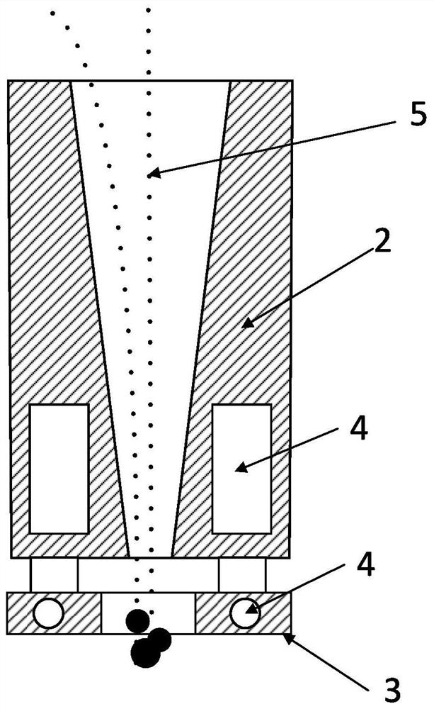
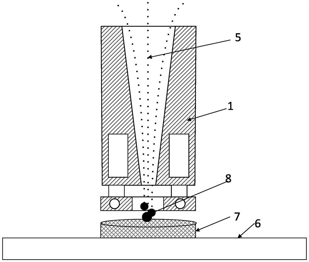
[0033]The invention provides a direct writing induction melting molding nozzle, such as Figure 1-2 As shown, the direct-writing induction melting molding nozzle 1 is an integrated structure with an internal powder feeding channel 2 and an induction coil 3, and the induction coil 3 is a high-frequency induction coil or an intermediate-frequency induction coil, which is fixedly arranged inside The outlet end of powder feeding channel 1. The shape of the internal powder feeding channel 2 requires that the cross-section of the channel be any polygon or a closed curve, and the size of the internal powder feeding channel 2 requires that a single metal powder 5 with the largest particle size can pass through without hindrance. A cooling water circulation channel 4 is provided inside the outer wall of the internal powder feeding channel 2 and inside the induction coil 3...


PUM


Abstract

The invention provides a direct writing type metal three-dimensional printing forming method based on induction smelting. The method comprises the steps that a CAD data file of a three-dimensional printing forming part, a forming substrate, metal powder and a direct writing type induction melting forming nozzle are prepared; inner vector line filling is carried out on a closed skeleton diagram ofeach layer of section; a spraying valve corresponding to the current section is controllably opened, the metal powder flows out through an inner powder conveying channel, and through rapid heating smelting of an induction coil, metal drops are formed and near vertically impact the current forming surface of the forming substrate; along the track of the inner filled vector line segment, the directwriting type induction melting forming nozzle and the forming substrate relatively displace, a continuous forming line segment consistent with the inner filled vector line segment is formed, and layer-by-layer stacking is carried out to finish forming. Forming is achieved through relative motion of the nozzle and the forming substrate, the forming size is not limited, precise forming of a large-size part is achieved, the method is flexible and convenient to implement, and the freedom degree is high.

Description

technical field [0001] The invention belongs to the technical field of additive manufacturing, and in particular relates to a direct-writing metal three-dimensional printing forming method based on induction melting. Background technique [0002] 3D printing (additive manufacturing) technology is actually a general term for a series of rapid prototyping technologies for parts. The coordinates discontinuously make the displacement of the thickness of the layer, and finally form a three-dimensional workpiece. The current rapid prototyping technologies on the market are divided into 3DP technology, FDM fusion lamination molding technology, SLA stereolithography technology, SLS selective laser sintering technology, DLP laser forming technology and UV ultraviolet forming technology. [0003] Due to the high melting point of metals, 3D printing technology for metal materials requires high-energy-density laser beams or electron beams as heat sources. With the development of scien...

Claims


Application Information

Patent Timeline
Patent Type & Authority Patents(China)
IPC IPC(8): B22F3/115B33Y30/00B33Y10/00
CPCB22F3/003B22F3/115B33Y10/00B33Y30/00
Inventor 薛伟嵇旭曹宇杨焕叶总一刘文文潘俏菲
Owner 佛山市创界模型科技有限公司
Why Eureka
Try Eureka