A Partitioned Parallel 3D Printing Forming Method for Large Precision Metal Parts

A technology of three-dimensional printing and metal parts, which is applied in the field of additive manufacturing, can solve the problems of inability to realize parallel molding, stress accumulation, slow molding speed, etc., and achieve the elimination of molding thermal stress problems, elimination of residual stress accumulation, and reduction of surface roughness Effect

Active Publication Date: 2020-09-29
江苏柏灵激光智能设备有限公司
View PDF4 Cites 0 Cited by
  • Summary
  • Abstract
  • Description
  • Claims
  • Application Information

AI Technical Summary

Problems solved by technology

[0008] In the existing technology, all kinds of metal 3D printing technologies basically use metal powder as the molding raw material, which needs to rely on the irradiation of external high-energy beams (laser beams or electron beams) to make the powder melt and then solidify and form. The disadvantages are: 1) The molding process needs to rely on linear scanning of single or multiple high-energy beams. For each high-energy beam, the powder on its scanning path is sequentially melted and solidified for molding. Parallel molding cannot be realized in essence, so the molding speed is slow and the efficiency is low. ; 2) Due to the low electro-optical conversion efficiency of lasers and electron beam sources (generally less than 20%), and the high melting point of metal powder, the energy density required for molding is extremely high, and the actual energy consumption is very high; 3) Due to the use of It is a micron-sized metal powder. The high melting point of the powder makes the metallurgical quality of the molten pool and the surface roughness of the molding process not high, and is prone to defects such as residual stress accumulation, thermal stress deformation, and internal thermal cracks; 4) due to thermal stress deformation The problem is that the size of the molded parts is limited, otherwise the molded parts that meet the dimensional accuracy requirements cannot be obtained

Method used


Image

  • A Partitioned Parallel 3D Printing Forming Method for Large Precision Metal Parts
  • A Partitioned Parallel 3D Printing Forming Method for Large Precision Metal Parts
  • A Partitioned Parallel 3D Printing Forming Method for Large Precision Metal Parts

Examples


Embodiment Construction

[0036] The present invention will be described in further detail below in combination with specific embodiments.

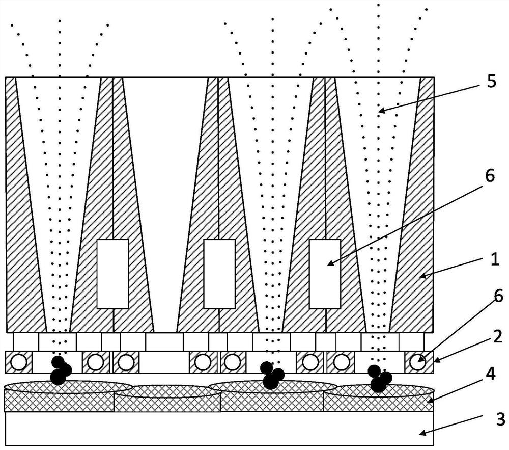
[0037] Such as figure 1 As shown, the present invention provides a metal powder induction smelting forming array plate, which includes a parallel nozzle array composed of several powder feeding nozzles 1 and an induction coil 2, and the induction coil 2 is a high-frequency induction coil or an intermediate-frequency induction coil , there are multiple induction coils 2, and the number of them is required to be equal to the number of powder feeding nozzles 1. Each induction coil 2 is fixedly arranged at the exit end of each powder feeding nozzle 1 in one-to-one correspondence, so that the number of induction coils 2 The center of the magnetic field is located on the central axis of the exit end of the powder feeding nozzle 1 .

[0038] A cooling water circulation channel 6 is provided inside the outer wall of the powder feeding nozzle 1 and inside the induction co...


PUM

PropertyMeasurementUnit
particle diameteraaaaaaaaaa

Abstract

The invention provides a large precision metal part partitioning parallel type three-dimensional printing forming method. The method comprises the steps that CAD data files of three-dimensional printing forming parts, a forming substrate, metal powder and a metal powder induction smelting forming array board are prepared; all layered slices are divided into multiple closed contour graph blocks; all the closed contour graph blocks are subjected to internal block filling; each small block in each closed contour graph block is filled through relative motion between a parallel nozzle array and theforming substrate; the forming parts are stacked from bottom to top layer by layer. Accordingly, the layered slices of large parts are flexibly divided into multiple graph blocks, by means of relative motion of the parallel type metal powder induction smelting forming array board and the forming substrate, area array projection powder parallel spraying forming is conducted on all the graph blocksin sequence, the forming size is not limited in principle, and the precision forming of any large-size part can be achieved.

Description

technical field [0001] The invention belongs to the technical field of additive manufacturing, and in particular relates to a partitioned parallel three-dimensional printing forming method for large precision metal parts. Background technique [0002] 3D printing (additive manufacturing) technology is actually a general term for a series of rapid prototyping technologies for parts. The coordinates discontinuously make the displacement of the thickness of the layer, and finally form a three-dimensional workpiece. The current rapid prototyping technologies on the market are divided into 3DP technology, FDM fusion lamination molding technology, SLA stereolithography technology, SLS selective laser sintering technology, DLP laser forming technology and UV ultraviolet forming technology. [0003] Due to the high melting point of metals, 3D printing technology for metal materials requires high-energy-density laser beams or electron beams as heat sources. With the development of ...

Claims


Application Information

Patent Timeline
Patent Type & Authority Patents(China)
IPC IPC(8): B22F3/115B33Y10/00B33Y30/00
CPCB22F3/003B22F3/115B33Y10/00B33Y30/00
Inventor 于艳玲
Owner 江苏柏灵激光智能设备有限公司
Why Eureka
Try Eureka