Plate positioning device of plate shearing machine

A technology of positioning device and shearing machine, which is applied to the attachment of shearing machines, shearing devices, shearing machine equipment, etc., which can solve the problems of laborious, unsuitable for large-scale shearing operations, and many steps

Inactive Publication Date: 2018-08-17
WUHU TIANMENG INFORMATION TECH CO LTD
View PDF0 Cites 16 Cited by
  • Summary
  • Abstract
  • Description
  • Claims
  • Application Information

AI Technical Summary

Problems solved by technology

[0002] The shearing machine uses a moving upper blade and a fixed lower blade, and adopts a reasonable blade gap to apply shearing force to metal plates of various thicknesses, so that the plates are broken and separated according to the required size. The existing shearing machine is in progress Before cutting the board, manually measure, position and mark on the board according to the required size, and then put it into the shearing machine to complete the shearing. Traditional equipment and shearing methods require many manual steps and are laborious, so they are not suitable for large-scale shearing. board work

Method used


Image

  • Plate positioning device of plate shearing machine
  • Plate positioning device of plate shearing machine
  • Plate positioning device of plate shearing machine

Examples


specific Embodiment approach

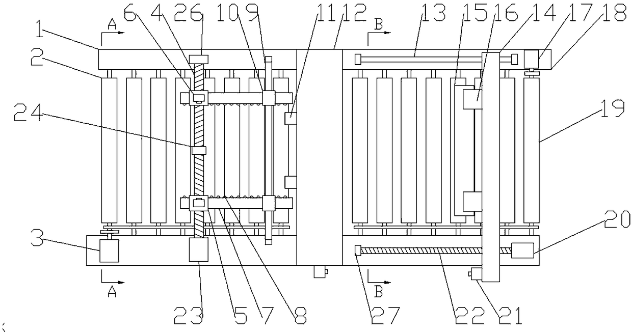
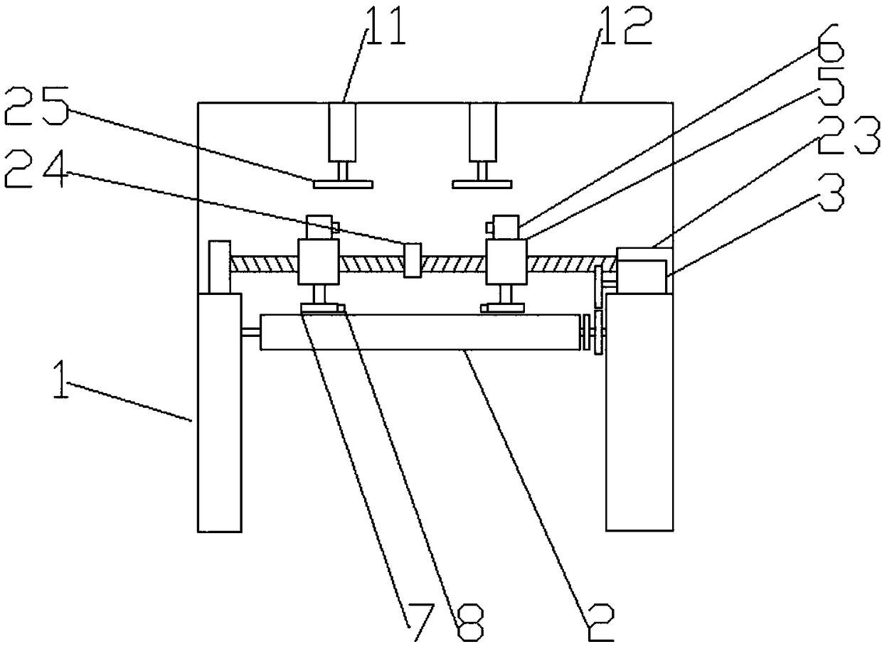
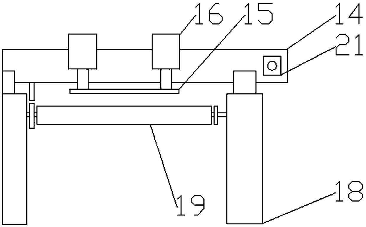
[0015] Figure 1-3 A specific embodiment of the present invention is shown: a plate positioning device for a shearing machine, comprising a shearing machine body 12, a front support 1 is provided at the front end of the shearing machine body 12, and a rear support 18 is provided at the rear end. Front support 1 one end is provided with screw mandrel seat one 26, and the other end is provided with servo motor one 3 and servo motor four 23, and described screw mandrel seat one 26 is provided with two-way screw mandrel 4, and described two-way screw mandrel 4 one end is connected with servo motor Motor four 23 are connected, and described two-way screw mandrel 4 is provided with symmetrical sliding seat 5, and described sliding seat 5 is provided with two distance sensors one probe, and described front bracket 1 upper end is also provided with two-way screw mandrel 4 parallel. The slide bar-9 is provided with a symmetrical slider 10 on the slide bar-9, the lower end of the slide ...


PUM


Abstract

The invention discloses a plate positioning device of a plate shearing machine. The plate positioning device comprises a plate shearing machine body, wherein a front bracket is arranged at the front end of the plate shearing machine body, a rear bracket is arranged at the rear end of the plate shearing machine body, and a first screw rod seat is arranged at one end of the front bracket, a first servo motor and a fourth servo motor are arranged at the other end of the front bracket, a bidirectional screw rod is arranged in the first screw rod seat, symmetrical sliding seats are arranged on thebidirectional screw rod, and two first distance sensor probes are arranged on the sliding seats. A first sliding rod is arranged at the upper end of the front bracket, symmetrical sliding blocks are arranged on the first sliding rod, first transverse plates are arranged at the lower ends of the sliding seats and the sliding blocks, a second sliding rod and a second servo motor are arranged at oneend of the rear bracket, and a second screw rod seat and a third servo motor are arranged at the other end of the rear bracket. A screw rod is arranged in the second screw rod seat, a sliding table isarranged on the screw rod, second air cylinders are arranged on the sliding table, and second transverse plates are arranged on the second air cylinders. Two second distance sensor probes are arranged at one end of the plate shearing machine body and one ends of the sliding seats. The positioning process of the plate positioning device is accurate and efficient, the manual operation steps are reduced, the efficiency of batch plate shearing is improved, and the plate positioning device is suitable for large batch of repeated plate shearing operations in factories.

Description

technical field [0001] The invention relates to the field of auxiliary devices of a shearing machine, in particular to a plate positioning device of a shearing machine. Background technique [0002] The shearing machine uses a moving upper blade and a fixed lower blade, and adopts a reasonable blade gap to apply shearing force to metal plates of various thicknesses, so that the plates are broken and separated according to the required size. The existing shearing machine is in progress Before cutting the board, manually measure, position and mark on the board according to the required size, and then put it into the shearing machine to complete the shearing. Traditional equipment and shearing methods require many manual steps and are laborious, so they are not suitable for large-scale shearing. Board work. Contents of the invention [0003] The technical problem to be solved by the present invention is to provide a plate positioning device of a plate shearing machine to sol...

Claims


Application Information

Patent Timeline
Patent Type & Authority Applications(China)
IPC IPC(8): B23D15/08B23D33/02
CPCB23D15/08B23D33/02
Inventor 张贵平
Owner WUHU TIANMENG INFORMATION TECH CO LTD
Why Eureka
Try Eureka