Plate shearing mechanism of plate shearing machine

A shearing machine and shearing technology, applied in the field of machinery, can solve the problems of limited material range, fracture separation, weak impact resistance, etc., and achieve the effect of improving the safety of use, prolonging the service life, and strong impact resistance.

Inactive Publication Date: 2018-08-17
SUQIAN GENERAL MACHINERY
View PDF1 Cites 3 Cited by
  • Summary
  • Abstract
  • Description
  • Claims
  • Application Information

AI Technical Summary

Problems solved by technology

[0002] The shearing machine is a kind of equipment with a wide range of uses, mainly used in the metal processing industry. It fixes the steel plate through the pressing frame of the shearing machine, and uses the relative movement between the upper and lower blades to process metal plates of various thicknesses. Apply shear force to make the plates break and separate according to the required size. The application number is CN200920110268.5 utility model for a shearing machine protection device and a shearing machine with the device. When feeding materials, when the hand is about to enter the shearing machine, it is blocked by the protective screen, which structurally ensures that the accident of "hand eating" by the shearing machine will not occur and ensures the safety of production. At the same time, because the protective device is fixed on the shearing plate On the working table of the shearing machine, there is no relative movement of parts between it and the lower bed of the shearing machine, so the safety of production is reliably guaranteed, but its impact resistance is not strong, and there is no overcut protection device for the tool, so it can be used for Shears have a limited range of materials

Method used


Image

  • Plate shearing mechanism of plate shearing machine
  • Plate shearing mechanism of plate shearing machine

Examples


specific Embodiment approach

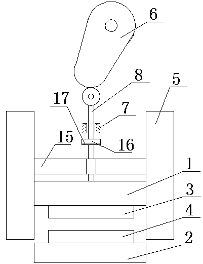
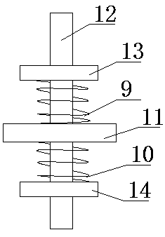
[0017] figure 1 with figure 2 A specific embodiment of the present invention is shown: a shearing mechanism of a shearing machine, including a moving tool seat 1, a fixed tool seat 2, a moving tool 3, a fixed tool 4, a buffer module 5, a cam 6, a slide rail 7 and a roller pusher Rod 8, the buffer module 5 has two, the two ends of the movable tool holder 1 are respectively connected with the two buffer modules 5, the cam 6 is connected to the frame through bearing rotation, and the slide rail 7 is fixedly connected On the frame, the bottom end of the roller push rod 8 is fixedly connected with the top end of the movable tool seat 1, and the top end of the roller push rod 8 is connected with the cam 6 by a line contact with the roller, and the movable tool 3 is connected with the movable tool seat 1. 1 is fixedly connected, the fixed tool 4 is fixedly connected to the top of the fixed tool seat 2, and the bottom end of the fixed tool seat 2 is fixedly connected to the frame. ...


PUM


Abstract

The invention discloses a plate shearing mechanism of a plate shearing machine and relates to the field of machinery. The plate shearing mechanism comprises a movable tool base, a fixed tool base, a movable tool, a fixed tool, two buffering modules, a cam, a sliding rail and a roller push rod, wherein the two ends of the movable tool base are connected with the two buffering modules separately; the cam is rotatably connected onto a rack through a bearing; the sliding rail is fixedly connected onto the rack; the bottom end of the roller push rod is fixedly connected with the top end of the movable tool base; the top end of the roller push rod is in line contact connection with the cam through an idler wheel; the movable tool is fixedly connected with the bottom end of the movable tool base;the fixed tool is fixedly connected with the top end of the fixed tool base; and the bottom end of the fixed tool base is fixedly connected with the rack. During working, the plate shearing mechanismis simple in structure, high in impact resistance capacity and high in plate shearing efficiency, can realize plate shearing with high intensity and is wider in range of application.

Description

technical field [0001] The invention relates to the mechanical field, in particular to a shearing mechanism of a shearing machine. Background technique [0002] The shearing machine is a kind of equipment with a wide range of uses, mainly used in the metal processing industry. It fixes the steel plate through the pressing frame of the shearing machine, and uses the relative movement between the upper and lower blades to process metal plates of various thicknesses. Apply shear force to make the plates break and separate according to the required size. The application number is CN200920110268.5 utility model for a shearing machine protection device and a shearing machine with the device. When feeding materials, when the hand is about to enter the shearing machine, it is blocked by the protective screen, which structurally ensures that the accident of "hand eating" by the shearing machine will not occur and ensures the safety of production. At the same time, because the protect...

Claims


Application Information

Patent Timeline
IPC IPC(8): B23D33/00B23D15/06
CPCB23D33/00B23D15/06
Inventor 杜爱民陈茂辉杜东亮唐运民
Owner SUQIAN GENERAL MACHINERY
Why Eureka
Try Eureka