Shaft with supporting, centering and pressurizing functions and gas turbine rotor

A technology for compressors and supporting shafts, applied to gas turbine devices, mechanical equipment, engine components, etc., can solve problems such as gas backflow, rotor rubbing, rotor scrapping, etc., to save materials, overcome pressure loss along the process, and rigidity matrix well-distributed effect

Pending Publication Date: 2018-08-17
GUIZHOU WISDOM ENERGY TECH CO LTD
View PDF0 Cites 1 Cited by
  • Summary
  • Abstract
  • Description
  • Claims
  • Application Information

AI Technical Summary

Problems solved by technology

In the event of minor faults or changes in combustion conditions, gas may flow back from the end, and the turbine discs and blades that lose cooling air flow are likely to rub against the stator under the action of thermal expansion
Moreover, the meshing between the two ends of the teeth is very dependent on the pre-tightening force of the bolts at both ends. When the end teeth are loose or the end teeth are severely worn, the function of the end teeth connection will fail, and the rotor will rub against the rotor when it is running at high speed. , and serious accidents in which the rotor is scrapped

Method used


Image

  • Shaft with supporting, centering and pressurizing functions and gas turbine rotor
  • Shaft with supporting, centering and pressurizing functions and gas turbine rotor
  • Shaft with supporting, centering and pressurizing functions and gas turbine rotor

Examples


Embodiment Construction

[0028] The embodiments of the present invention are described in detail below. This embodiment is implemented on the premise of the technical solution of the present invention, and detailed implementation methods and specific operating procedures are provided, but the protection scope of the present invention is not limited to the following implementation example.

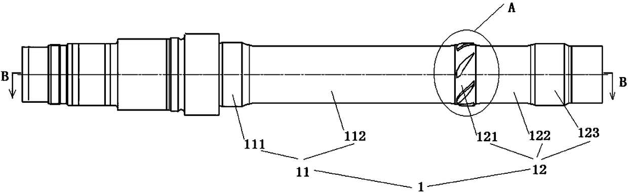
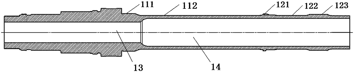
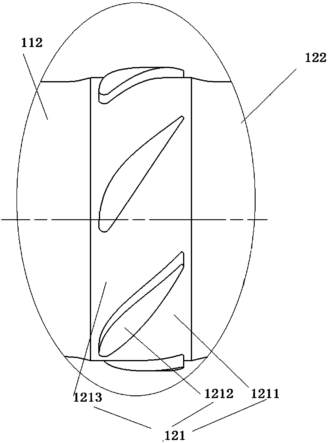
[0029] like figure 1 As shown, the present embodiment has a shaft 1 with support, centering and supercharging, and the shaft 1 includes a compressor installation part 11 and a turbine installation part 12 in sequence; the turbine installation part 12 includes a turbine support part connected to the turbine 3 121. The outer diameter of the turbine support part 121 is larger than the outer diameter of other parts of the adjacent shaft 1, and the turbine support part 121 is provided with a supercharging mechanism. The role of the turbine will fail, and at this time, the turbine support part 121 simultaneously realize...


PUM


Abstract

The invention discloses a shaft with supporting, centering and pressurizing functions and a gas turbine rotor. The shaft sequentially comprises a compressor installation part and a turbine installation part, the turbine installation part includes a turbine support part connected with a turbine, the outer diameter of the turbine support part is larger than that of other parts, adjacent to the turbine support part, of the shaft, and a pressurizing mechanism is arranged on the turbine support part. The shaft with the supporting, centering and pressurizing functions and the gas turbine rotor havethe beneficial effects that the structure and layout are simple, machining is easy, the supporting, centering and pressurizing functions can be achieved through the turbine support part, in the case of consuming a small amount of useful work, the deformation quantity of the rotor is reduced, the probability of collision between rotor parts and stator parts is reduced, the stability of the whole rotor is optimized, and best comprehensive benefits are achieved.

Description

technical field [0001] The invention relates to a shaft structure and a gas turbine rotor adopting the shaft structure, in particular to a shaft structure with support centering and supercharging and a gas turbine rotor adopting the shaft structure. Background technique [0002] At present, most gas turbine rotor stages are connected by end-tooth connection, and the function of end-tooth connection is to realize automatic centering and torque transmission during operation. At the same time, the hollow gap between the mountain-shaped teeth at the meshing position of the end teeth realizes the intake air from the compressor end, and leads to the end of the turbine disk through the gap between the shaft and the turbine disk to cool the turbine disk wall and blades, so as to optimize the rotor stability and Increase the service life of high temperature components. When the rotor speeds up, the bleed air pressure of the compressor is not high and the flow rate is small at low sp...

Claims


Application Information

Patent Timeline
IPC IPC(8): F01D5/06F01D25/28F02C3/06
CPCF01D5/06F01D25/28F02C3/06Y02T10/12
Inventor 王俊王志强
Owner GUIZHOU WISDOM ENERGY TECH CO LTD
Why Eureka
Try Eureka