Single-end-face built-in-type mechanical seal for centrifugal pump

A technology of mechanical seals and centrifugal pumps, which is applied to mechanical equipment, components of pumping devices for elastic fluids, pumps, etc., and can solve problems such as rubber rings are easy to wear and leak, life does not match, and cooling water consumes a large amount of water. , to achieve the effect of improving anti-leakage performance, increasing service life and saving cooling water

Pending Publication Date: 2018-08-17
宜兴市宙斯泵业有限公司
View PDF0 Cites 1 Cited by
  • Summary
  • Abstract
  • Description
  • Claims
  • Application Information

AI Technical Summary

Problems solved by technology

However, the rubber ring of the cooling water in the sealing device of the traditional technology is easy to wear and leak. Generally, after 2 to 3 months of use, the seals of the moving ring and the static ring at the front end are still intact, but the rubber sealing ring sealing the cooling water is worn and leaks the cooling water. Liquid, there is the leakage of cooling water for flushing the seal and the shortcomings of large cooling water consumption, which does not meet the requirements of environmental protection and water saving. The reasons for the above problems are: 1. The high pressure of cooling water makes the lip of the rubber sealing ring Enclose the shaft sleeve, and the wear is accelerated; 2. The rubber sealing ring in the sealing box is at a linear speed of about 5 m / s, and the natural use time is only 4 to 6 months. The life of the ring does not match the life of the cooling water sealing ring, and the life of the cooling water sealing ring is only one-third of the life of the mechanical seal), so this kind of mechanical seal is very inconvenient to use, but there is no substitute for a long-lasting anti-corrosion mechanical seal , so far this issue has not been resolved

Method used


Image

  • Single-end-face built-in-type mechanical seal for centrifugal pump
  • Single-end-face built-in-type mechanical seal for centrifugal pump
  • Single-end-face built-in-type mechanical seal for centrifugal pump

Examples


Embodiment 1

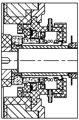
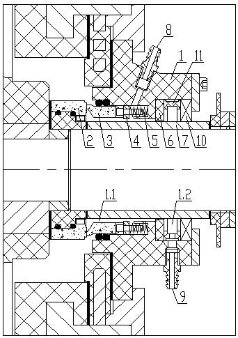
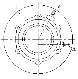
[0023] Such as figure 1 As shown, a single-end built-in mechanical seal for a centrifugal pump includes a seal box 1, a moving ring 2, a static ring 3, a static ring seat 4, a spring 5, a shaft sleeve 7, a cooling water inlet 8, and a cooling water outlet 9. The cooling water sealing ring 10, the mechanical seal is installed on the shaft sleeve 7, and the shaft sleeve 7 is sleeved on the main shaft. The inner wall of the moving ring 2 is provided with a concave step to cooperate with the convex step on the shaft sleeve 7 to limit the position , the static ring 3 is in contact with the end face of the dynamic ring 2 for sealing, the sealing box 1 is fixedly connected to the pump casing of the centrifugal pump for sealing, the spring 5 is installed in the sealing box 1 and connected with the static ring 3, the static ring 3 is set at the front end of the sealing box 1, and the static ring 3 is in contact with the sealing box 1 for sealing, the top contact surface of the static r...

Embodiment 2

[0025] Embodiment 2, with reference to Embodiment 1, another cooling water outlet 9.1 is provided at the high pressure zone 1.1.

Embodiment 3

[0026] Embodiment 3, referring to Embodiment 1, the sealing box 1 and the retaining ring 6 are integrally formed.


PUM


Abstract

The invention provides a single-end-face built-in-type mechanical seal for a centrifugal pump. A retaining ring is arranged between a static ring and a cooling water sealing ring, a cooling water flowcavity is divided into two zones of the high pressure zone and the low pressure zone through the retaining ring, the static ring is located in the high pressure zone, the cooling water sealing ring is located in the low pressure zone, and the bottom end of the retaining ring gets close to a shaft sleeve to form an overflowing clearance. According to the single-end-face built-in-type mechanical seal for the centrifugal pump, external leakage of cooling water can be prevented through slight changing on the basis of the built-in-type mechanical seal of the pump, the service life of the cooling water sealing ring is prolonged, and the production cost does not need to be increased; and the cooling water can be saved by 50-80% by changing the hole diameter of a cooling water in-out opening, andthe great water-saving effect is achieved.

Description

technical field [0001] The invention relates to the mechanical industry, in particular to a single-end built-in mechanical seal device. Background technique [0002] Centrifugal pumps are used to transport liquids. The commonly used shaft seals include external mechanical seals and internal mechanical seals. Centrifugal pumps that transport slurry containing particles mostly use built-in mechanical seals with cooling water flushing. However, the rubber ring of the cooling water in the sealing device of the traditional technology is easy to wear and leak. Generally, after 2 to 3 months of use, the seals of the moving ring and the static ring at the front end are still intact, but the rubber sealing ring sealing the cooling water is worn and leaks the cooling water. Liquid, there is the leakage of cooling water for flushing the seal and the shortcomings of large cooling water consumption, which does not meet the requirements of environmental protection and water saving. The r...

Claims


Application Information

Patent Timeline
Patent Type & Authority Applications(China)
IPC IPC(8): F04D29/12F04D29/58F04D29/00
CPCF04D29/126F04D29/007F04D29/5886
Inventor 谭希平陈磊郭丹枫蒋龙福蒋凌超
Owner 宜兴市宙斯泵业有限公司
Why Eureka
Try Eureka