Improved streetlamp device

An improved street lamp technology, applied to lighting devices, lighting auxiliary devices, lighting device components, etc., can solve the problems of increased mains power consumption, inability to adjust, damage, etc., and achieve increased service life, convenient operation, and simple structure Effect

Inactive Publication Date: 2018-08-17
覃洁梅
View PDF5 Cites 0 Cited by
  • Summary
  • Abstract
  • Description
  • Claims
  • Application Information

AI Technical Summary

Problems solved by technology

[0002] With the continuous development of science and technology, some road lighting and street lamps are constantly improving, and these street lamps generally have one commonality, that is, they need to be connected to the mains before they can be used for lighting, which greatly increases the consumption of mains power and contributes to the national economy. It brings a certain burden. There are also some street lamp devices p

Method used


Image

  • Improved streetlamp device
  • Improved streetlamp device
  • Improved streetlamp device

Examples


Embodiment Construction

[0015] Combine below Figure 1-4 The present invention will be described in detail.

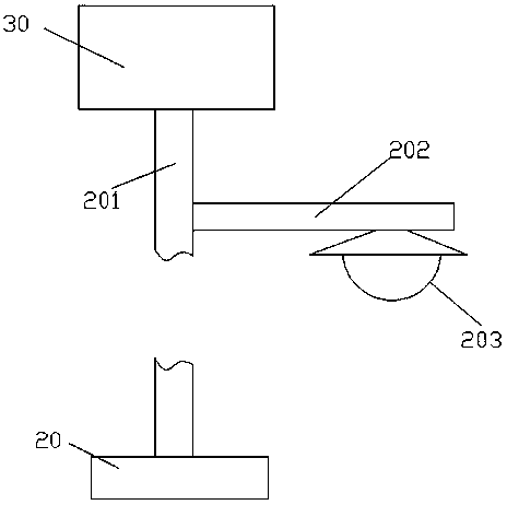
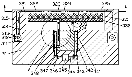
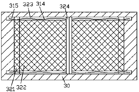
[0016] refer to Figure 1-4 , an improved street light device according to an embodiment of the present invention, comprising a fixing base 20 and a frame 30 fixed above the fixing base 20 through a lamp post 201, and the right side end of the lamp post 201 is extended to the right There is a lamp arm 202, the bottom end of the lamp arm 202 is provided with an LED bulb 203, the top end of the frame 30 is provided with a placement cavity 325, and the upper side of the inner wall of the front and rear sides of the placement cavity 325 is correspondingly provided with a second A chute 323, the inner walls of the left and right sides of the placement cavity 325 are correspondingly provided with telescopic grooves 321 intercommunicating with the first chute 323, and the outer sides of the telescopic groove 321 are correspondingly provided with through grooves 315 front and rear, and the telescopi...


PUM


Abstract

The invention discloses an improved streetlamp device. The improved streetlamp device comprises a fixed base and a rack. The rack is fixedly arranged on the upper part of the fixed base through a lamppole. A lamp arm is arranged on the right end face of the lamp pole in a rightward stretching manner. An LED lamp bulb is arranged on the bottom end face of the lamp arm. A placement chamber is formed in the top end face of the rack. First sliding grooves are correspondingly formed in the upper side in the inner wall on the front side and the upper side of the inner wall on the rear side of the placement chamber. Telescopic grooves are correspondingly formed in the inner wall of the left side and the inner wall of the right side of the placement chamber. Each telescopic groove and the corresponding first sliding groove communicate with each other. Through grooves are correspondingly formed in the front and the rear of the outer side of each telescopic groove. A first turning groove is formed in the extended tail part of the bottom of each telescopic groove, and communicates with the telescopic groove. A guide rod is installed in each first sliding groove between the front side and therear side in a smooth fit manner. Rope yarn is fixedly installed in the part, on the outer side of the corresponding guide rod, of each first sliding groove. Each rope yarn extends into the corresponding through groove and the corresponding first turning groove in sequence, and is fixedly connected with a winding roll arranged in the corresponding first turning groove. A first rotary shaft is fixedly installed between the winding roll on the front side and the winding roll on the rear side.

Description


Claims


Application Information

Patent Timeline
Owner 覃洁梅
Why Eureka
Try Eureka