Fire early-warning method and device

A technology of fire early warning and early warning information, which is applied to fire alarms that act by electricity, fire alarms that rely on radiation, and alarms, etc., can solve the problems of inability to detect early fire high-risk points and fire trends

Active Publication Date: 2018-08-17
CHNA ENERGY INVESTMENT CORP LTD +1
View PDF7 Cites 21 Cited by
  • Summary
  • Abstract
  • Description
  • Claims
  • Application Information

AI Technical Summary

Problems solved by technology

[0004] The embodiment of the present invention provides a fire early warning method and device to at least solve the problem that the prior art adopts the method of shooting vide...

Method used


Image

  • Fire early-warning method and device
  • Fire early-warning method and device
  • Fire early-warning method and device

Examples


Embodiment 1

[0021] According to an embodiment of the present invention, an embodiment of a fire early warning method is provided. It should be noted that the steps shown in the flowcharts of the accompanying drawings can be executed in a computer system such as a set of computer-executable instructions, and, although in The flowcharts show a logical order, but in some cases the steps shown or described may be performed in an order different from that shown or described herein.

[0022] figure 1 It is a flow chart of a fire early warning method according to an embodiment of the present invention, such as figure 1 As shown, the method includes the following steps:

[0023] Step S102, acquiring a visible light image of the region to be detected.

[0024] As an optional embodiment, the area to be detected may be, but not limited to, the production equipment site of the coal-to-oil system. Since the coal-to-oil production process is carried out under high temperature and high pressure envir...

Embodiment 2

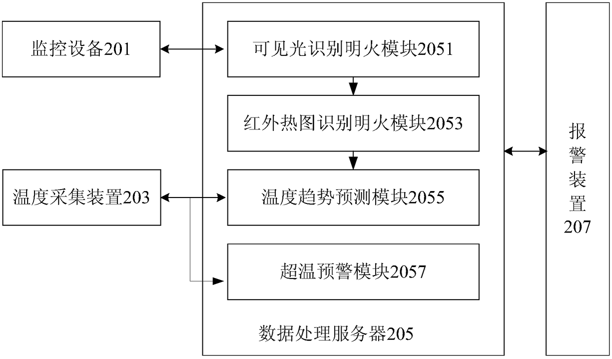
[0110] According to an embodiment of the present invention, an embodiment of a device for realizing the above-mentioned fire early warning method is also provided, Figure 7 is a schematic diagram of a fire early warning device according to an embodiment of the present invention, such as Figure 7 As shown, the device includes: a first acquisition module 701 , an analysis module 703 , a second acquisition module 705 , a processing module 707 and a first detection module 709 .

[0111] Wherein, the first acquisition module 701 is used to acquire the visible light image of the region to be detected;

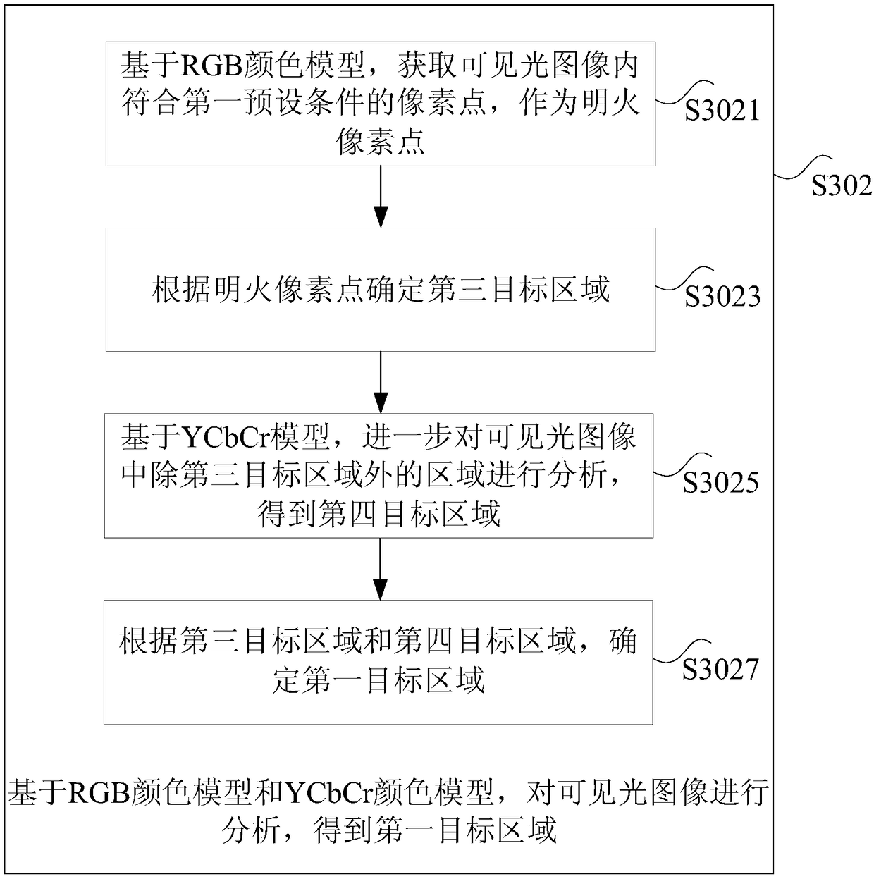
[0112] The analysis module 703 is configured to analyze the visible light image based on a preset algorithm model to obtain a first target area, wherein the first target area is one or more areas determined within the area to be detected where open flames have appeared and / or open flames are about to appear. regions;

[0113] The second acquisition module 705 is configured to acq...

Embodiment 3

[0124] According to an embodiment of the present invention, a storage medium is also provided, and the storage medium includes a stored program, wherein the program executes any optional or preferred fire warning method in Embodiment 1.


PUM


Abstract

The invention discloses a fire early-warning method and device. The method comprises the steps: obtaining a visible image of a to-be-detected region; carrying out the analysis of the visible image based on a predicted algorithm model, obtaining a first target region, wherein the first target region is one region (or more regions) in which open fire is determined to already appear and/or is about to appear in the to-be-detected region; obtaining an infrared thermal image of the first target region; carrying out the processing of the infrared thermal image, obtaining a second target region, wherein the target region is one region (or more regions) in which open fire is determined to already appear and/or is about to appear in the first target region; detecting the temperature change conditions of the second target region, and determining whether to output the early warning information or not according to the temperature change conditions. According to the invention, the method solves a technical problem that a scheme of employing a fire site photographing mode for detecting the fire in the prior art causes a condition that an early fire high-risk point which does not form open fire and the fire trend cannot be detected.

Description

technical field [0001] The invention relates to the field of fire detection, in particular to a fire early warning method and device. Background technique [0002] The coal-to-liquids production process is carried out under high temperature and high pressure environment. Most of the raw materials, products, semi-finished products and by-products are combustible solids, gases or liquids, all of which have the risk of fire and explosion. For this potential safety hazard, the more mature monitoring technologies currently used include: temperature-sensing, smoke-sensing, and photo-sensing detectors combined with fire detection algorithms and other technologies, which use temperature, smoke, and brightness to analyze and distinguish open flames. Due to the influence of space, area and harsh environment in the existing technology, it is more difficult to extract the characteristics of open flames, resulting in an increase in the false alarm rate. In the fire detection technology ...

Claims


Application Information

Patent Timeline
IPC IPC(8): G08B17/12G08B17/06G08B29/18
CPCG08B17/06G08B17/12G08B29/186G08B29/188
Inventor 王建立刘继臻田勇李会英白天祥张华松刘永孙希华杨志强
Owner CHNA ENERGY INVESTMENT CORP LTD
Why Eureka
Try Eureka