Fixing piece and fixing method for large-size annular bonded NdFeB magnet cutting and shaping

A large-size, NdFeB technology, which is applied in the field of large-size annular bonded NdFeB magnet cutting and repairing fixtures and fixings, can solve problems such as poor clamping accuracy, low clamping efficiency, and easy powder jamming. Achieve the effect of long service life, reasonable structure design and automation

Pending Publication Date: 2018-08-21
CHINA NUCLEAR TIANJIN TECH DEV
View PDF14 Cites 1 Cited by
  • Summary
  • Abstract
  • Description
  • Claims
  • Application Information

AI Technical Summary

Problems solved by technology

[0003] The purpose of the present invention is to provide a large-size annular bonded NdFeB magnet cutting and repairing fixture for the problem that traditional chucks are easy to jam powder in the cutting and repairing process of bonded NdFeB magnets in the prior art;
[0004] Another object of the present invention is to provide a large-size annular bonded Nd-Fe-B magnet cutting and repairing fixture for the problems of low clamping efficiency and poor clamping accuracy of the traditional three-jaw chuck. method

Method used


Image

  • Fixing piece and fixing method for large-size annular bonded NdFeB magnet cutting and shaping
  • Fixing piece and fixing method for large-size annular bonded NdFeB magnet cutting and shaping
  • Fixing piece and fixing method for large-size annular bonded NdFeB magnet cutting and shaping

Examples


Embodiment 1

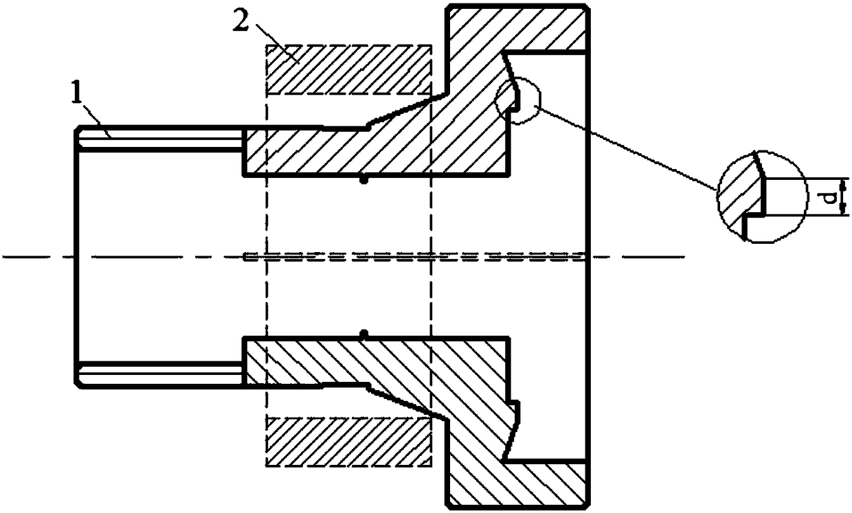
[0042] like Figure 1-2 As shown, a kind of large-size annular bonded NdFeB magnet cutting and repairing fixture of the present invention includes a chuck 1 and a clamp 2 for constraining the chuck 1 to realize its expansion and clamping, wherein:

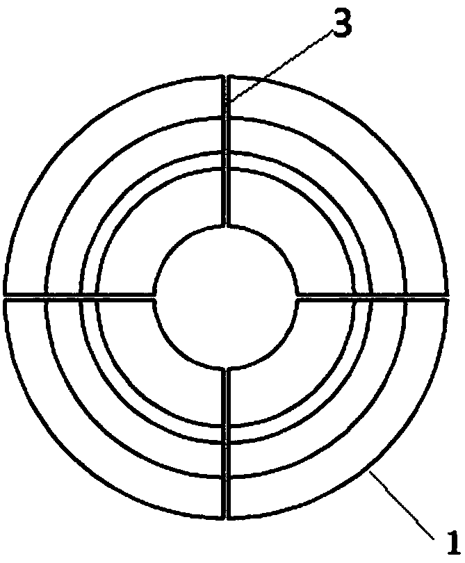
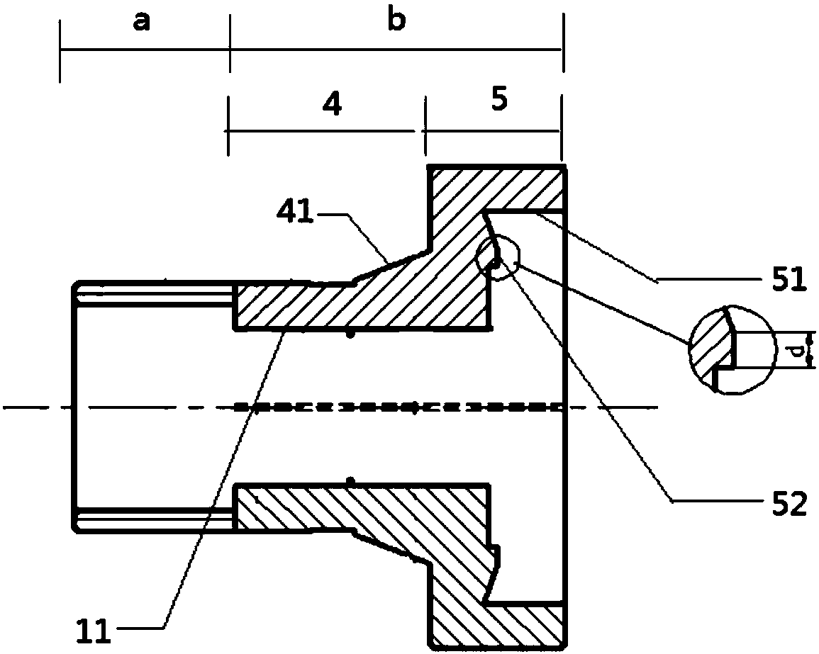
[0043] like Figure 2-3 As shown, the axial center of the chuck 1 is provided with a cavity 11, including a connecting portion a and a positioning portion b, and the side wall of the positioning portion is provided with at least one clamp for realizing expansion and contraction of the positioning portion. The groove 3, the positioning part b includes an enabling section 4 and a snap ring section 5, the outer wall of the enabling section 4 is provided with a tapered surface 41, and the front part of the snap ring section 5 is formed with a The fixed cavity 51, the bottom end of the fixed cavity 51 is provided with a protruding fixed surface 52;

[0044] The clamp 2 is sleeved on the outside of the chuck 1, and relatively moves alo...

Embodiment 2

[0056] In order to increase the contact area between the clamp 2 and the chuck 1 and reduce the contact stress, this embodiment is improved on the basis of embodiment 1, as Figure 4 As shown, the clamp 2 includes a ring structure, and the inner wall of the ring structure is provided with a driving tapered surface 21 .

Embodiment 3

[0058] This embodiment is improved on the basis of embodiment 1 or 2, as Figure 5 As shown, the inside of the fixing surface 54 is provided with a right-angle groove 53 , and the outside of the fixing surface 54 is provided with a V-shaped groove 54 .

[0059] The arrangement of the right-angle groove 53 and the V-shaped groove 54 can effectively reduce the width of the positioning surface, and the setting of the V-shaped groove 54 can make the debris generated by the mode cutting remain on the positioning surface 52, and the debris can be removed under the influence of its own gravity. Slide down along the slope of the V-shaped groove 54 under the action.

[0060] As a preferred manner, the included angle of the V-shaped surface of the V-shaped groove 54 is an acute angle, and the angle is 30°-60°.

[0061] As a preferred mode, the material of the chuck 1 is 65Mn steel, which is quenched at 800°C and then tempered at a medium temperature of 320°C to ensure that the chuck has ...


PUM


Abstract

The invention discloses a fixing piece and fixing method for large-size annular bonded NdFeB magnet cutting and shaping. The fixing piece comprises a chuck and a hoop which is used for restraining thechuck to achieve expanding and clamping of the chuck, wherein a cavity is formed in the axis position of the chuck, the chuck comprises a connecting part and a positioning part, the side wall of thepositioning part is provided with at least one clamping groove used for achieving expanding and retracting of the positioning part, the positioning part comprises a driving segment and a snap ring segment, the outer wall of the driving segment is provided with a tapered face, the front portion of the snap ring segment is provided with a fixing cavity used for positioning an annular piece, and thebottom end of the fixing cavity is provided with a protruding fixing face; and the exterior of the chuck is sleeved with the hoop, the hoop does relative movement along the tapered face to achieve expanding and clamping of the chuck. The fixing piece has the beneficial effect of being long in service life.

Description

technical field [0001] The invention relates to the technical field of chuck tooling, in particular to a fixing piece and a fixing method for cutting and repairing large-size annular bonded NdFeB magnets. Background technique [0002] Bonded NdFeB magnets are formed by bonding tiny NdFeB magnetic powder particles together with a certain binder. The diameter of the magnetic powder is small, generally 0.05mm to 0.15mm, so powdery chips are easy to enter the card during cutting and repairing. In the guide rail of the disc, it will cause the chuck to jam, which will affect the clamping and positioning accuracy of the chuck, and cause the size of the magnet to be out of tolerance after repairing, which will affect the repairing efficiency of the magnet in industrial production. Therefore, it is necessary to design a special chuck for cutting and repairing large-size annular bonded NdFeB magnets to ensure the efficiency of magnet repair operations. Contents of the invention [...

Claims


Application Information

Patent Timeline
Patent Type & Authority Applications(China)
IPC IPC(8): B23B31/02
CPCB23B31/02
Inventor 郭志伟许海肖凯业郑文
Owner CHINA NUCLEAR TIANJIN TECH DEV
Why Eureka
Try Eureka