


Quick Research
Generate reliable direction feasibility study reports for your R&D in just a few steps.

Technical Q&A
Discover and master advanced knowledge NOW. Basics, ideas, possibilities, all at once.

Find Solutions
As an expert in R&D theories, this can generate solutions to your technical problems instantly.

Evaluate Feasibility
Analyze your overall solution with one click, know your potential R&D risks in advance.

Monitor Landscape
Get weekly tech updates, stay abreast of the latest tech innovations and key insights.
Foundation prefabricated column and connection structure and construction method thereof
A basic structure and prefabricated column technology, applied in the field of building foundation, can solve the problems of exceeding the position deviation of the exposed screw on the top, affecting the connection quality of steel structure columns, failing to meet the bearing capacity requirements, etc., achieving fast and efficient construction, saving consumption, and easy construction. Effect
- Summary
- Abstract
- Description
- Claims
- Application Information
AI Technical Summary
Problems solved by technology
Method used
Image

Examples
Embodiment 1
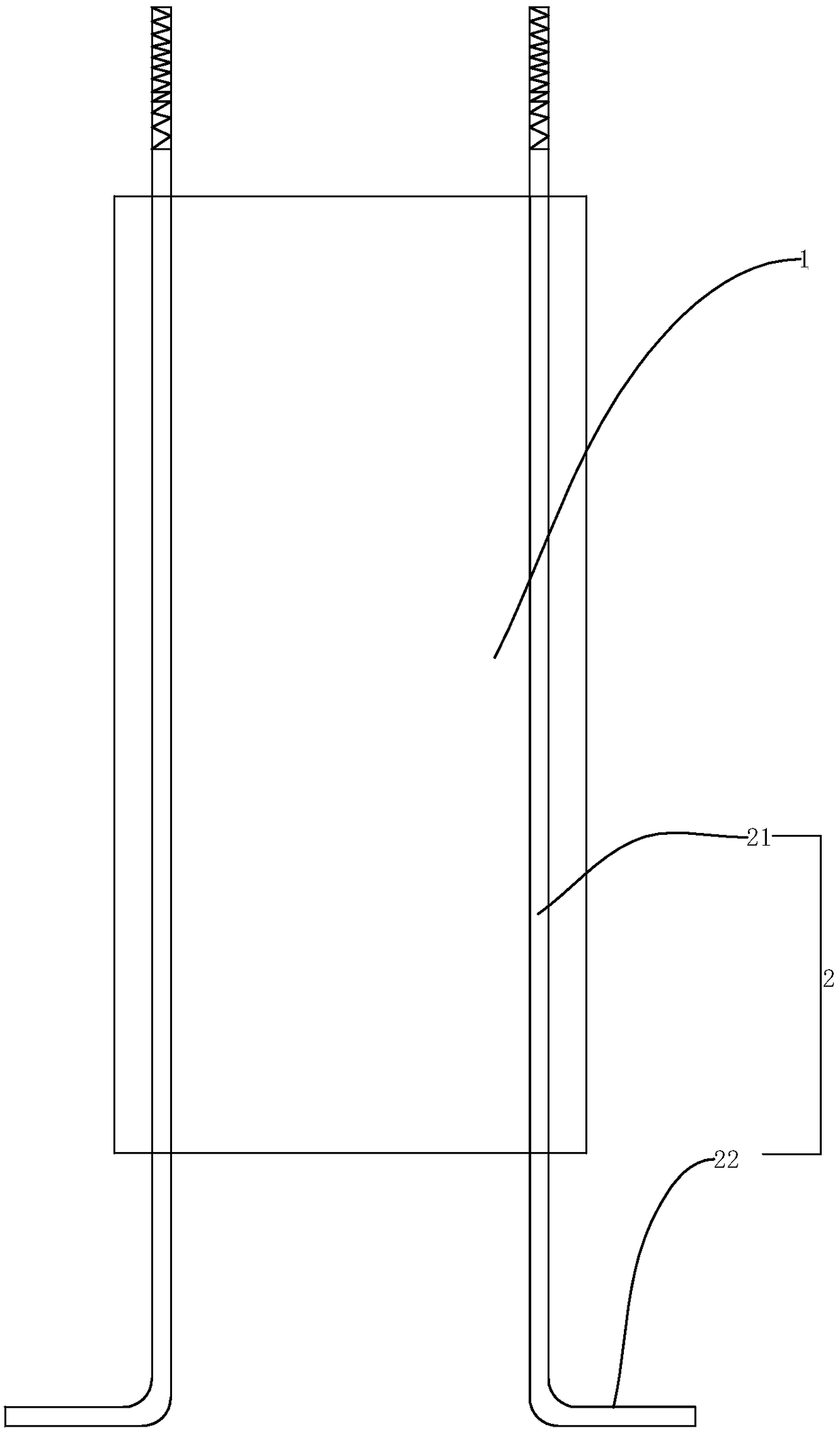
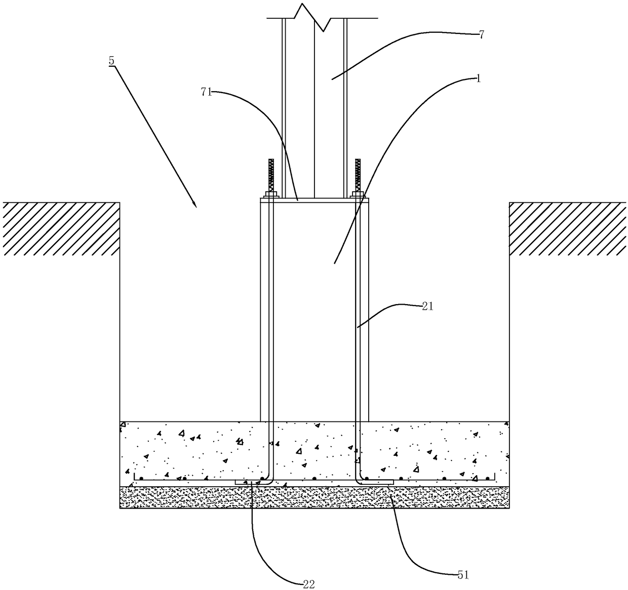
[0068] A foundation prefabricated column such as figure 1 As shown, it includes a column body 1 and anchor bolts 2. The anchor bolts 2 are poured inside the column body 1, and include a vertically arranged rod part 21 and a leg 22 perpendicular to the rod part 21. The rod part 21 and the leg part 22 are integrated Formed structure, the upper end of the rod part 21 protrudes from the cylinder 1 and is placed above the cylinder 1, and the top part of the rod part 21 can be a bolt head. The rod portion 21 of the anchor bolt 2 protrudes downwards from the bottom surface of the column body 1 , and the leg 22 is located outside the column body 1 .
[0069] Such as figure 2 As shown, during installation, a cushion layer is poured at the bottom of the foundation pit 5 and a reinforcement mesh is arranged, and then the foundation prefabricated column is hoisted into the foundation pit 5. After adjusting the position and height, the feet 22 are connected and fixed with the reinforceme...
Embodiment 2
[0078] Reminisce figure 2 , the top of the foundation is threadedly connected with the steel plate 71 fixed on the bottom of the H-shaped steel 7 by the anchor bolt 2 to achieve the purpose of fixing the H-shaped steel 7. Because the anchor bolt 2 is prone to breakage under the condition of bearing a large shear stress, so if Figure 7 As shown, the lower end of the steel plate 71 fixed with the H-shaped steel 7 is welded with a shear pile 72 , and the shear pile 72 is arranged perpendicular to the steel plate 71 . In the prior art, when the foundation is poured, a mold will be placed at the center of the upper end to pour out the positioning holes 4 corresponding to the shear piles 72. When the H-shaped steel 7 is installed, the shear piles 72 will be inserted into the positioning holes 4, and finally the steel plate Concrete is poured in the gap between 71 and the foundation and in the positioning hole 4 to achieve the purpose of bearing shear stress.
[0079] Such as F...
Embodiment 3
[0083] The difference from Example 1 is that, if Figure 12 and Figure 13 As shown, it also includes a prefabricated ground beam 8 arranged on the side of the column body 1, and the prefabricated ground beam 8 connects two adjacent foundation prefabricated columns. The prefabricated ground beams 8 are pre-embedded with ground beam connecting ribs 81 in the horizontal direction, and the ground beam connecting ribs 81 are connected with the foundation prefabricated columns. A foundation post-cast belt is set between the end of the prefabricated ground beam 8 and the column body 1, and after the concrete is poured, the prefabricated ground beam 8 is connected to the foundation as a whole.
[0084] The ground beam connecting bars 81 and the column connecting bars 11 can be connected by conventional fixed connection methods such as binding connection, welding, straight thread sleeve 101 connection and the like.
[0085] Such as Figure 14 As shown, the end of the ground beam co...
PUM
 Abstract
Description
Claims
Application Information
 - R&D Engineer
- R&D Manager
- IP Professional
- Industry Leading Data Capabilities
- Powerful AI technology
- Patent DNA Extraction
Browse by: Latest US Patents, China's latest patents, Technical Efficacy Thesaurus, Application Domain, Technology Topic, Popular Technical Reports.
© 2024 PatSnap. All rights reserved.Legal|Privacy policy|Modern Slavery Act Transparency Statement|Sitemap|About US| Contact US: help@patsnap.com