Toilet water tank valve and design method

A valve and water tank technology, used in flushing equipment with water tanks, water supply devices, buildings, etc., can solve the problems of complex valve structure, and achieve the effect of flexible installation position, high flushing pressure, and small flushing pressure loss.

Inactive Publication Date: 2018-08-21
ZHEJIANG KEZHUDA MACHINERY TECH CO LTD
View PDF1 Cites 0 Cited by
  • Summary
  • Abstract
  • Description
  • Claims
  • Application Information

AI Technical Summary

Problems solved by technology

[0003] In the above-mentioned patent application technology, the water tank has two valves, and the valve structure is complicated. Two parts of force are required to control the two valves, and the human body directly controls the gravity of the gravity transmission plate of the valve.

Method used


Image

  • Toilet water tank valve and design method
  • Toilet water tank valve and design method
  • Toilet water tank valve and design method

Examples


Embodiment Construction

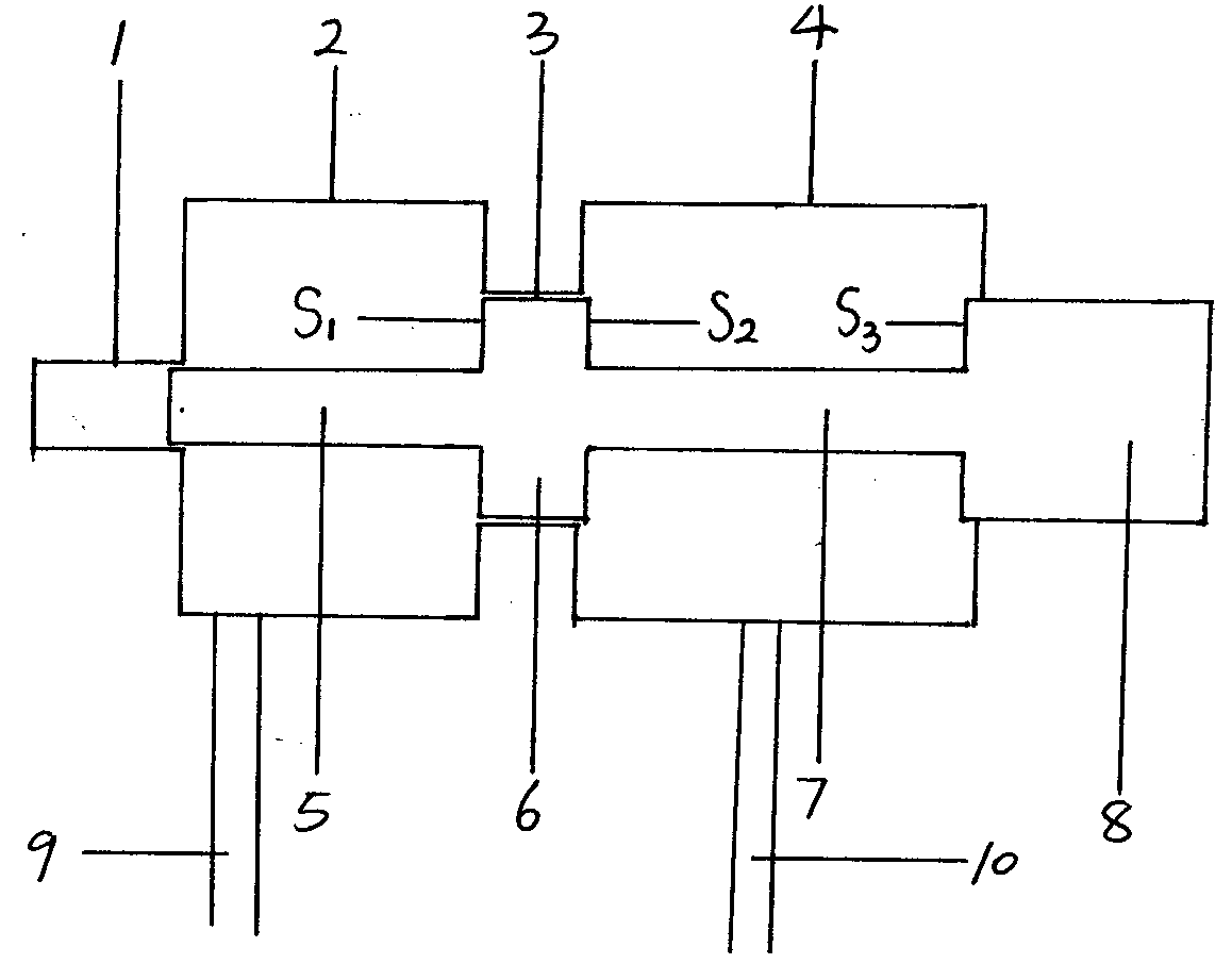
[0030] There are two types of normally closed valves, the first structure is:

[0031] The normally closed valve includes a valve cavity, a valve plug, an inlet and outlet pipe, a shaft hole, a tail shaft, and a through hole. The valve cavity has a first through hole 3, and the first through hole divides the cavity into a front cavity 4 and a first through hole. The rear cavity 2 has a first shaft hole 1, and the valve plug is composed of four parts from front to back: the first front part 8, the first middle part 7, the first sealing part 6, the first Valve plug tail shaft 5, the first front part is sealed through the front cavity, the first middle part and the first sealing part are located in the cavity, the first middle part is thinner than the first sealing part and the first front part, and the first middle part is thinner than the first sealing part and the first front part. When the first sealing part is located in the first through hole, it forms a sealed water-blocki...


PUM


Abstract

The invention discloses a toilet water tank valve and a design method, and belongs to the field of toilets. The valve does not include a spring; a shaft hole is arranged in the rear cavity of the valve, and a tail shaft is arranged at the rear of a valve plug; the tail shaft corresponds to the shaft hole, and has a sliding sealing structure; the tail shaft can make the axial movement of the valveplug being more concentric. More importantly, a cross section of the tail of the valve plug is not subject to water pressure. For valve plugs that are subjected to the same water pressure recovery force, the valve plug with the tail shaft has a larger valve plug diameter than the valve shaft without the tail shaft. In this way, the valve cavity has a larger through hole, and the valve can have a larger cross-sectional area of the flow passage, so that flushing pressure loss of the water tank is small and the flushing pressure is greater.

Description

technical field [0001] The invention belongs to the field of toilets. Background technique [0002] The invention relates to the field of closets, in particular to a closet water tank valve in the Chinese patent application with publication number CN 104164908A. [0003] In the above-mentioned patent application technology, the water tank has two valves, and the valve structure is complicated. Two parts of force are required to control the two valves, and the human body directly controls the gravity of the gravity transmission plate of the valve. Contents of the invention [0004] The invention relates to a toilet water tank valve and a design method thereof. [0005] The valve design method of the toilet water tank of the present invention has simple structure and low cost. The valve does not include a spring, the valve plug is affected by an external force, the valve plug moves from the front cavity to the bottom of the rear cavity, the valve state changes, the ext...

Claims


Application Information

Patent Timeline
Patent Type & Authority Applications(China)
IPC IPC(8): E03D1/36E03D5/02
CPCE03D1/36E03D5/024
Inventor 王永强
Owner ZHEJIANG KEZHUDA MACHINERY TECH CO LTD
Why Eureka
Try Eureka