Intelligent optical switching door electronic look

An electronic lock and intelligent technology, which is applied to building locks, non-mechanical transmission-operated locks, buildings, etc., can solve the problems of equipment and resources that cannot be found in time, high failure rate and maintenance cost, and difficult maintenance, so as to improve automation Degree and lock operation safety, good tamper-proof effect, simple structure effect

Active Publication Date: 2018-08-21
CHANGZHOU TAIPING COMM SCI & TECH
View PDF14 Cites 2 Cited by
  • Summary
  • Abstract
  • Description
  • Claims
  • Application Information

AI Technical Summary

Problems solved by technology

The optical cable transfer box is usually placed in a passive environment in the wild. The surrounding conditions are complicated, and it is easy to be damaged by irrelevant personnel. It is not easy to maintain, illegal opening of the box door, theft of equipment and resources in the box cannot be found in time, and the key management is out of control. state
At the same time, the quality of the construction workers who carry out the installation and maintenance work is also uneven. In order to save trouble and do not carry out standardized operations, some construction workers often directly break the door and forcibly open the outdoor equipment or do not close the door after the installation and maintenance work. These behaviors will cause outdoor equipment destroyed, resulting in loss
At present, the door lock of the optical cable transfer box adopts a mechanical lock, and the management and maintenance are completely dependent on manual work. The utilization rate of optical fiber resources is low, and the failure rate and maintenance cost are high. At the same time, there is a lack of effective monitoring and guarantee methods for the status of passive facilities.
The other uses electronic door locks and electronic keys for management. The unlocking signals of electronic door locks and electronic keys are encrypted by encryption algorithms to unlock, which can improve the security and management efficiency of smart door locks, but electronic locks require manual work. On-site opening, not remote unlocking

Method used


Image

  • Intelligent optical switching door electronic look
  • Intelligent optical switching door electronic look
  • Intelligent optical switching door electronic look

Examples


Embodiment Construction

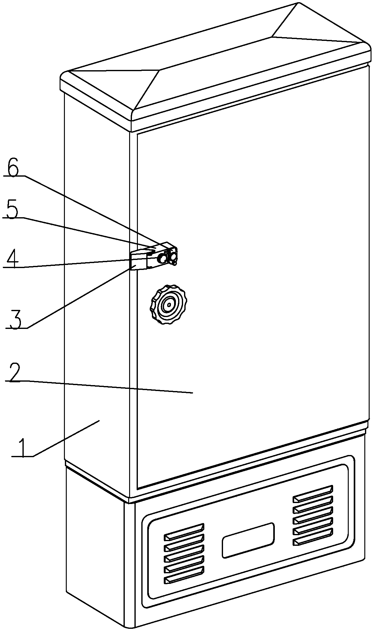
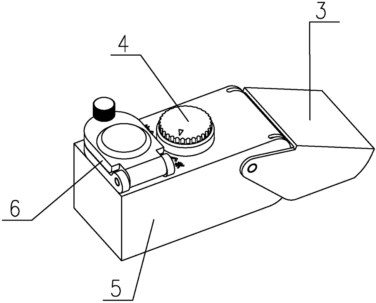
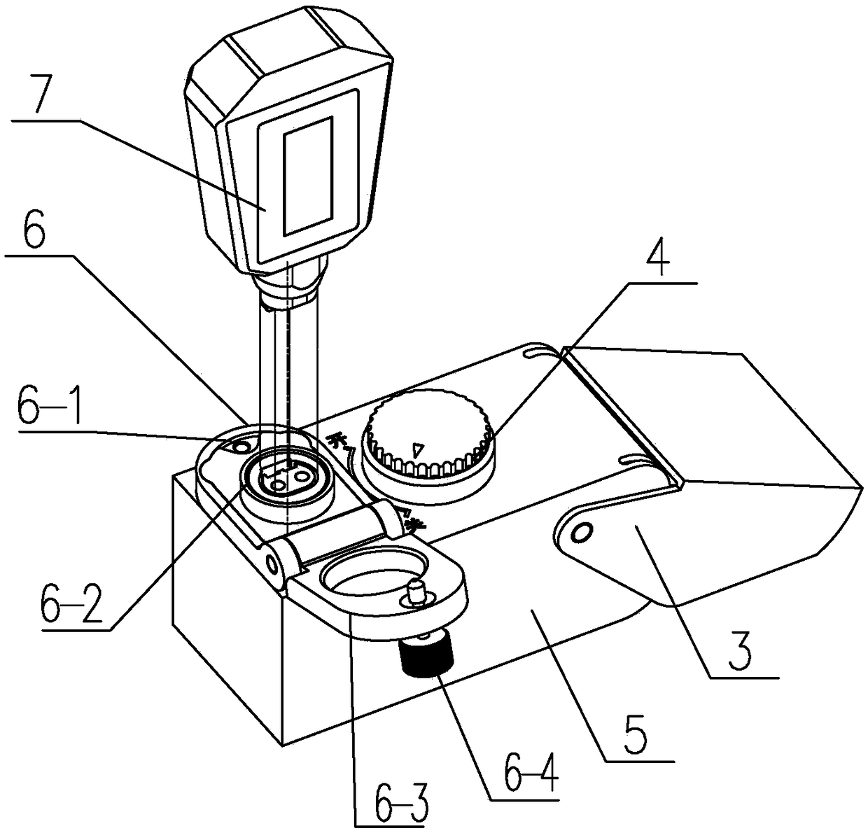
[0028] See figure 1 , 2 As shown, the intelligent optical door electronic lock of the present invention includes a lock base 5, a box lock 9, and a first lockset and a second lockset installed on the lock base 5, and further improves safety through the different functions of the two locksets. Performance, and can meet the requirements of on-site unlocking and remote automatic unlocking.

[0029] See figure 1 , 9 As shown, the lock base 5 of the present invention is installed on the box door 2, and the box lock catch 9 is installed on the box body 1, and the first lockset and the second lockset are installed on the lock base 5, see Figure 1~4 , 7, 9, the lock seat 5 of the present invention includes a movable base 5-2 and a fixed seat 5-1 for fixing on the door 2, and the fixed seat 5-1 includes a base and two side plates and The top plate can be provided with mounting holes on the bottom plate, which can be installed on the box body 1 through fasteners, or the fixed seat ...


PUM


Abstract

The invention relates to an intelligent optical switching door electronic look. A movable substrate of a lock seat is hinged to the outer side of a permanent seat and covers the permanent seat; a lockcover is hinged to the permanent seat or/and the movable substrate; a first lock comprises a motor and a mechanical lock cylinder; the mechanical lock cylinder is installed on the movable substrate;the motor is installed on the permanent seat; a second lock is an electronic lock and is installed on the movable substrate; the motor shell of the motor is provided with a cavity and at least two guide slots; a spring is installed in the cavity of the motor shell and is used for supporting a motor core; the mechanical lock cylinder is positioned on the upper part of the motor core; a magnetic lock block is installed in the respectively corresponding guide slot; each magnetic lock block corresponds to respective magnetic induction ring arranged in the motor shell; the magnetic lock blocks areused for locking or unlocking the shoulder of a lock shaft, and a path through which the shoulder passes is arranged between every two magnetic lock blocks. The intelligent optical switching door electronic look has the characteristics of reasonable structure and high safety, the unlocking of the electronic lock can be met, and remote unlocking can be met.

Description

technical field [0001] The invention relates to an intelligent optical communication door electronic lock, which belongs to the technical field of optical communication equipment. Background technique [0002] The optical cable transfer box has the functions of wiring, welding, fiber storage, and fiber adjustment. It has the performance of tenaciously resisting the field environment, and can withstand severe climate changes and harsh working environments. The box body has good sealing performance and the protection level reaches IP65. Require. The optical cable transfer box is usually placed in a passive environment in the wild. The surrounding conditions are complicated, and it is easy to be damaged by irrelevant personnel. It is not easy to maintain, illegal opening of the box door, theft of equipment and resources in the box cannot be found in time, and the key management is out of control. state. At the same time, the quality of the construction workers who carry out t...

Claims


Application Information

Patent Timeline
Patent Type & Authority Applications(China)
IPC IPC(8): E05B65/52E05B65/02E05B65/06E05B47/00E05B17/20E05B63/14E05B17/22E05B15/00
CPCE05B15/00E05B17/2084E05B17/22E05B47/0012E05B63/146E05B65/025E05B65/06E05B2047/0084
Inventor 张国强石新根吴锦辉任献忠王立军
Owner CHANGZHOU TAIPING COMM SCI & TECH
Why Eureka
Try Eureka