Light-small pipe rod conveying device and working method thereof

A light and small technology for conveying equipment, applied in the direction of drilling equipment, drill pipes, drill pipes, etc., can solve the problems of small turning angle of V-shaped grooves, failure of sucker rods to roll out, poor roundness of sucker rods, etc., to achieve increased The effect of large push stroke, reduction of total equipment length, and reduction of production materials

Pending Publication Date: 2018-08-21
JIANGSU SHENLIDA MACHINERY MFR
View PDF0 Cites 3 Cited by
  • Summary
  • Abstract
  • Description
  • Claims
  • Application Information

AI Technical Summary

Problems solved by technology

[0004] However, it is unreasonable to adopt such a structure for the conveyor at the small workover site, because such a model is long in length and relatively heavy in weight, and requires a long truck to be towed away. Generally, one well needs to be completed on the same day for small workover work. Quick loading and unloading equipment is needed, and such models are long and heavy, and the transportation cost is high; in addition, there are oil pipes and sucker rods in small workover wells, and the sucker rods themselves have poor roundness and poor rolling ability. The groove turning angle is small, and the sucker rod cannot be rolled out; in summary, the existing pipe and rod conveying equipment cannot meet the needs of small workover

Method used


Image

  • Light-small pipe rod conveying device and working method thereof
  • Light-small pipe rod conveying device and working method thereof
  • Light-small pipe rod conveying device and working method thereof

Examples


Embodiment

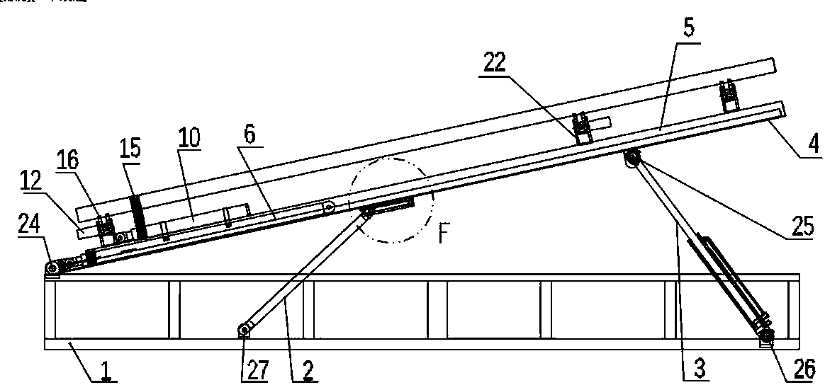
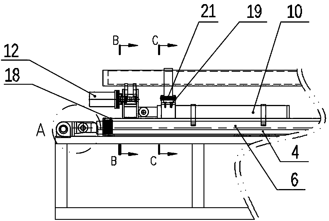
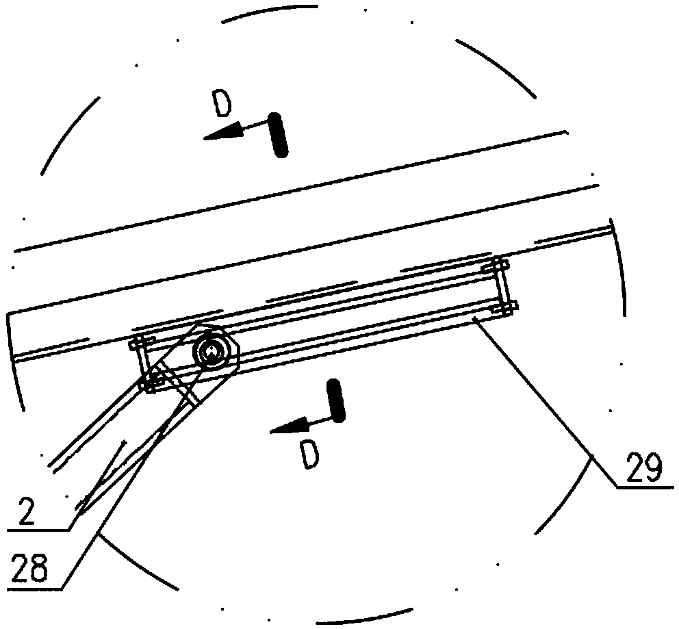
[0034] A kind of light and small pipe rod conveying equipment of the present invention, such as Figure 1 to Figure 8As shown, it includes a frame 1, a lifting device 3, a sliding base 4, a sliding part 5 and a propulsion device 6, and the sliding part 5 moves linearly on the sliding base 4 under the action of the propulsion device 6, and the sliding part 5, a feeding structure is provided above, and the feeding structure is connected with the slider 5 through an overturning and sliding device; Drive device 10, described feeding structure comprises upper feeding chute 9 and lower feeding chute 11; The first wobble plate 15 is connected between described upper feeding chute 9 and sliding driving device 10, and described lower feeding chute 11 is connected with turning drive The devices 12 are connected by a second swing plate 16 . The first wobble plate 15 is V-shaped, and the second wobble plate 16 is Y-shaped.

[0035] In this embodiment, one end of the sliding base 4 is hi...


PUM


Abstract

The invention discloses a light-small pipe rod conveying device which comprises a frame, a lifting device, a sliding base, a sliding part and a pushing device. The sliding part linearly moves on the sliding base under the action of the pushing device, a feeding structure is arranged above the sliding part and connected with the sliding part through an overturning and sliding device, the overturning and sliding device comprises a supporting plate, an overturning drive device and a sliding drive device, the overturning drive device and the sliding drive device are arranged on the supporting plate, the feeding structure comprises an upper feeding groove and a lower feeding groove, the upper feeding groove is connected with the sliding drive device through a first swinging plate, and the lowerfeeding groove is connected with the overturning drive device through a second swinging plate. Sufficient total pushing strokes and stability in the conveying process of pipe rods are ensured when the total length and total weight of the device are decreased, and energy consumption and cost in use are reduced.

Description

technical field [0001] The invention relates to the technical field of special equipment for the petroleum industry, in particular to a light and small pipe rod conveying equipment. Background technique [0002] In the workover site of oil drilling and workover, the use of pipe and rod conveying equipment is gradually promoted, the purpose is to realize the transmission of pipe and rod (oil pipe, tools, drill pipe, etc.) from the wellhead to the pipe bridge. It has high working efficiency, well protects the threaded thread of the pipe rod, and is safer than the previous manual dragging method. [0003] The existing pipe rod conveying equipment generally adopts the following structure. The rocking rod is pushed by the lifting cylinder. When the rocking rod swings to an angle, the upper part of the entire frame is raised as a whole, and stops when it rises to a predetermined height; Pushing, that is, the V-shaped pipe groove is pushed by the propulsion cylinder, and the pipe ...

Claims


Application Information

Patent Timeline
Patent Type & Authority Applications(China)
IPC IPC(8): E21B19/14
CPCE21B19/14
Inventor 张秀红
Owner JIANGSU SHENLIDA MACHINERY MFR
Why Eureka
Try Eureka