
Patsnap Eureka
For R&D, Patsnap Eureka makes reading and utilizing patents & technical documents easy.
Patsnap Eureka AIR
Designed for self-driven R&D workflows. Generate viable solutions, solve complex R&D challenges, empower your innovation with AI.

Patsnap Eureka Materials
Designed for material experts only. Revolutionize your material R&D, from search, analyze, to developing new materials.

TechResearch
Generate reliable direction feasibility study reports for your R&D in just a few steps.

TechSeek
Discover and master advanced knowledge NOW. Basics, ideas, possibilities, all at once.

TechMind
As an expert in R&D Theories, TechMind can generates customized viable solutions instantly.

TechRisk
Analyze your overall solution with one click, know your potential R&D risks in advance.

TechMonitor
Get weekly tech updates, stay abreast of the latest tech innovations and key insights.
Room pressure control system and method
A technology of control system and control method, applied in the direction of heating and ventilation control system, heating and ventilation safety system, heating method, etc.
- Summary
- Abstract
- Description
- Claims
- Application Information
AI Technical Summary
Problems solved by technology
Method used
Image

Examples
no. 1 Embodiment
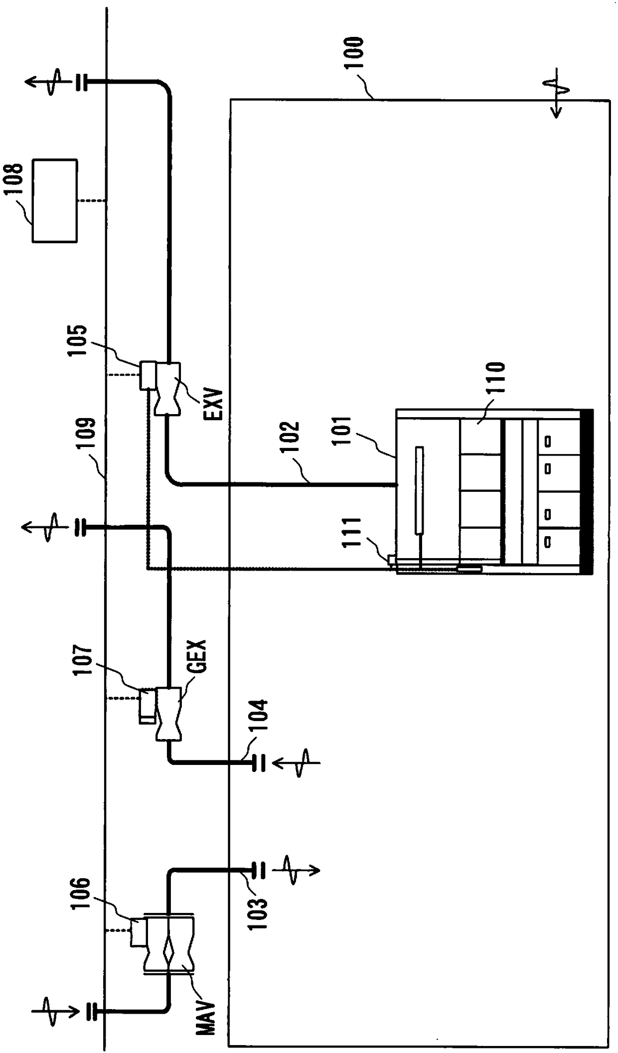
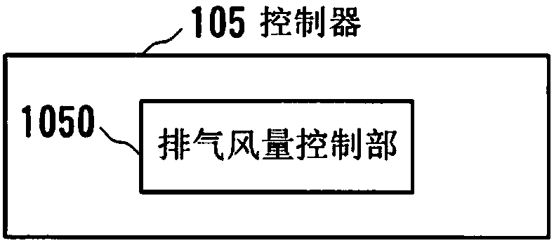
[0030] Hereinafter, embodiments of the present invention will be described with reference to the drawings. figure 1 It is a block diagram showing the configuration of the room pressure control system according to the first embodiment of the present invention. The room pressure control system of this embodiment has: a fume hood, which is arranged in the room 100; a local exhaust duct 102, which is connected to the fume hood 101; an air supply duct 103, which provides air supply to the room 100; Duct 104, which discharges the air in the room 100; local exhaust valve EXV, which adjusts the air volume of the local exhaust duct 102; air supply valve MAV, which adjusts the air volume of the air supply duct 103; general exhaust valve GEX , which adjusts the air volume of the general exhaust pipe 104; the controller 105, which controls the local exhaust valve EXV; the controller 106, which controls the air supply valve MAV; the controller 107, which controls the general exhaust valve ...
no. 2 Embodiment
[0052] In the first embodiment, the case where the supply air volume Vmav is changed due to the opening and closing of the local exhaust valve EXV accompanying the opening and closing of the regulating door 110 of the fume hood 101 has been exemplified, but the reason for the change of the supply air volume Vmav is still unknown. There are others, and for all of these reasons the invention is applicable. As another example of changing the air supply air volume Vmav, there is a possibility of reducing the air supply air volume Vmav while maintaining a constant pressure difference between indoor and outdoor in order to save energy during nights when no work is performed, holidays, and other time periods when there are no people present. and the air volume switching control of the exhaust air volume Vgex. This air volume change is performed every day on weekdays. In the example of switching from daytime to nighttime, both the supply air volume Vmav and exhaust air volume Vgex gr...
no. 3 Embodiment
[0063] Next, a third embodiment of the present invention will be described. In this embodiment, as another example of changing the supply air volume Vmav, a case where the supply air volume Vmav is changed by temperature control will be described. Figure 9 It is a block diagram showing the configuration of the room pressure control system according to this embodiment. In this embodiment, since the configuration of the controllers 105, 107, 108 is the same as that of the first embodiment, the figure 2 , Figure 4 , Figure 5 symbols are explained.
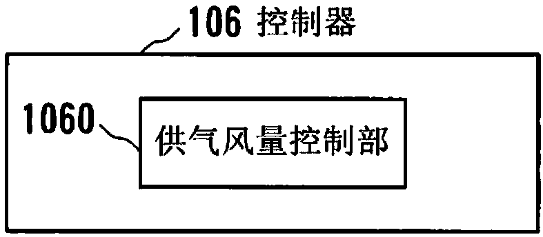
[0064] Figure 10 It is a block diagram showing a configuration example of the controller 106 of this embodiment. The controller 106 of this embodiment includes: a supply air volume control unit 1060 ; and an air volume calculation unit 1061 , which calculates the supply air volume Vmav according to the load condition of the room 100 .
[0065] Figure 11 It is a flowchart explaining the temperature control operation of thi...
PUM
 Abstract
Description
Claims
Application Information
 - R&D Engineer
- R&D Manager
- IP Professional
- Industry Leading Data Capabilities
- Powerful AI technology
- Patent DNA Extraction
Browse by: Latest US Patents, China's latest patents, Technical Efficacy Thesaurus, Application Domain, Technology Topic, Popular Technical Reports.
© 2024 PatSnap. All rights reserved.Legal|Privacy policy|Modern Slavery Act Transparency Statement|Sitemap|About US| Contact US: help@patsnap.com