
Visible air flow indicator and method for measuring air volume of deodorizing air duct

An air flow and indicator technology, which is applied in volume indication and recording equipment, volume/mass flow generated by mechanical effects, etc., can solve the problems that cannot be popularized and used in a large scale, the cost is high, and the relative size of the air volume of the deodorizing air duct cannot be displayed and other issues to achieve the effect of conveniently reading traffic data

Pending Publication Date: 2018-08-21
SHANGHAI MUNICIPAL ENG DESIGN INST GRP
View PDF0 Cites 1 Cited by
  • Summary
  • Abstract
  • Description
  • Claims
  • Application Information

AI Technical Summary

Problems solved by technology

[0002] At present, the air flow indicator in the traditional deodorizing air duct uses three red ribbons or flame-like airflow belts to observe whether there is gas discharged from the air duct, which has the following defects: 1) The air flow indicator cannot display the deodorizing wind The relative size of the air volume in the pipe; 2) The flame-like airflow zone will block the return of condensed water, causing condensed water to accumulate on the pipe for a long time, causing corrosion to the pipe
[0003] However, the flowmeters that can accurately display the readings are expensive and cannot be widely used

Method used


Image

  • Visible air flow indicator and method for measuring air volume of deodorizing air duct
  • Visible air flow indicator and method for measuring air volume of deodorizing air duct
  • Visible air flow indicator and method for measuring air volume of deodorizing air duct

Examples


Embodiment Construction

[0028] The present invention will be further described below in conjunction with the accompanying drawings.

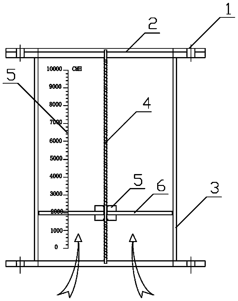
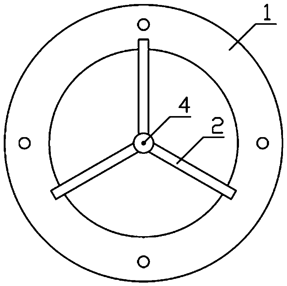
[0029] Such as figure 1 As shown, a visual air flow indicator includes a flange cover plate 1, a bracket 2, and a cylinder body 3. The flange cover plate 1 is fixed on the upper and lower ends of the cylinder body 3 and is concentric with the cylinder body 3. Shaft 4, the fixed shaft 4 is fixed at the center of the barrel body 2 through the bracket 2, the fixed shaft 4 passes through the middle of the bearing 5, the bearing is embedded in the bearing seat 5 and can freely rotate up and down along the fixed shaft, The air disk 6 is fixed on the bearing seat 5, so that the air disk 6 can freely rotate up and down around the axis in the cylinder 3, and the air flow can be read directly and accurately on the scale 7 through the position of the air disk 6 . The cylinder body 3 is made of transparent material so that the position of the wind disk 6 in the cylinder body can...


PUM

PropertyMeasurementUnit
Slopeaaaaaaaaaa

Abstract

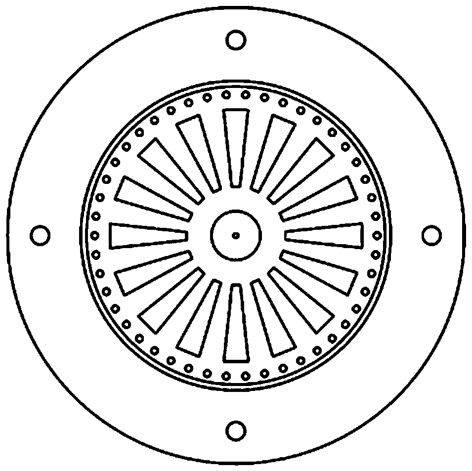
The invention discloses a visible air flow indicator. A fixing shaft is arranged on a transparent cylinder; a wind disk is mounted on the fixing shaft through a bearing and can rotate around the fixing shaft; a plurality of air holes are formed in the wind disk; a scale is arranged on a side surface of the transparent cylinder; air enters the transparent cylinder from the bottom of the cylinder, and when the air passes through the air holes formed in the wind disk, the wind disk is driven to rotate, so that the wind disk is hovered in the transparent cylinder; and the air volume is obtained through the position corresponding to the scale, of the wind disk. The visible air flow indicator has the advantages that: the deodorizing air duct has the visible air flow indicator, and the air volumeof the deodorizing air duct can be instantly and accurately read out by observing the scale, thereby realizing the adjustment of the air volume of the deodorizing air duct on site; the cost of the visible air flow indicator is much lower than that of the vortex-type and plug-in gas flowmeters on the market; and the visible air flow indicator is more convenient to read the flow data, and is a major breakthrough in the monitoring of the air volume of the deodorizing air ducts in constructed sewage treatment plants.

Description

technical field [0001] The invention relates to the technical field of monitoring the wind speed of a deodorizing air duct, in particular to a visual air flow indicator. Background technique [0002] At present, the air flow indicator in the traditional deodorizing air duct uses three red ribbons or flame-like airflow belts to observe whether there is gas discharged from the air duct, which has the following defects: 1) The air flow indicator cannot display the deodorizing wind The relative size of the air volume in the pipe; 2) The flame-like airflow zone will block the return flow of condensed water, causing condensed water to accumulate on the pipe for a long time and cause corrosion to the pipe. [0003] However, a flowmeter that can accurately display readings is expensive and cannot be widely used. Contents of the invention [0004] The purpose of the present invention is to provide a visual air flow indicator, which can intuitively and accurately read the air volum...

Claims


Application Information

Patent Timeline
IPC IPC(8): G01F1/05G01F15/06
CPCG01F1/05G01F15/06
Inventor 张欣杜炯戴小平董磊郑贤正李庆桂
Owner SHANGHAI MUNICIPAL ENG DESIGN INST GRP
Learn More