Modular, multi-stage, integral sealed motor pump with integrally-cooled motors and independently controlled rotor speeds

a sealed, multi-stage technology, applied in the field of pumps, can solve problems such as rotordynamic problems, source of leakage and other failure modes, alignment problems between the driving motor and the mechanical seal,

Inactive Publication Date: 2019-04-25
FLOWSERVE MANAGEMENT CO
View PDF28 Cites 7 Cited by
  • Summary
  • Abstract
  • Description
  • Claims
  • Application Information

AI Technical Summary

Benefits of technology

[0011]An integral motor pump module is disclosed that directs the discharge of process fluid from the rotor over the surface of the motor housing, thereby reducing or eliminating any need for a separate, dedicated motor cooling flow path. In embodiments, more than 80% of the fluid that enters the module inlet is directed through a discharge path to the module outlet, and at least 20% of the motor housing is in direct contact with the discharge path. In embodiments, more than 90% of the fluid that enters the module flows from the inlet to the outlet through the discharge path, and more than 50% of the motor housing is in direct contact with the discharge path. In various embodiments, more than 80% of the motor housing is in direct contact with the discharge path.
[0016]Rotors in other embodiments include induction motors that utilize non-permanent magnets, such as “squirrel cage” rotor coils in which currents are induced by the stator electromagnets during pump operation. Torque is thereby transmitted directly from the electromagnet stator coils of the motor to the rotor without the use of a rotating shaft. In embodiments, the motor coils are sealed from the working fluid using static sealing methods, which eliminates any need for dynamic mechanical seals, and avoids the problems of alignment, leakage, and / or maintenance that would otherwise arise therefrom.
[0017]Axial and radial locating of the rotor is provided in embodiments by product-lubricated bearings on each rotor stage. By using individual bearings in embodiments for each rotor stage, the bearings in each stage can be designed to handle the loads from that stage only, and the risk of overloading bearings from combined stage loading in a multistage arrangement is completely eliminated. Using the working fluid as a lubricant for the bearings in embodiments eliminates the need for an external oil lubrication system and greatly simplifies the overall pump design.
[0018]Motor cooling in embodiments directed to pumping of heated process fluid can be further augmented by including an externally cooled fluid path through which either process fluid or a separate, dedicated cooling fluid is circulated. Fluid cooling of the motor allows higher performance limits and greater power density in the overall pump.
[0020]Embodiments include a plurality of variable frequency drives (VFD's), and in some of these embodiments the motor in each stage of the pump is independently controlled by a dedicated VFD. One of the key benefits in some of these embodiments is that the first stage can run at lower speeds than the rest of the pump, so as to accommodate low net positive suction head (“NPSH”) and off-peak conditions. In some applications, varying the speed of only the final stage provides a useful approach precisely controlling the output pressure and / or flow.
[0024]In embodiments, one way thrust bearings are used in place of separate axial and radial bearings. Pump stage embodiments include stationary shafts inserted through the impeller hub and threaded into the pump stage housing, which facilitates easy assembly and maintenance without special tools. Using a sensorless motor along with an appropriate VFD also reduces the instrumentation required on each stage in various embodiments.

Problems solved by technology

Pumps with high stage counts or a vertical arrangement can use very long shafts that lead to various rotordynamic issues related to shaft deflections and critical speeds.
These seals are a source of leakage and other failure modes.
Even with rigid baseplates, nozzle loads on the pump can cause alignment problems between the driving motor and mechanical seals.
However, these designs still suffer from issues arising from the use of a single, long shaft to drive all of the pump stages, and they still require careful alignment of the motor with the pump housing so as to couple the motor and pump shafts as efficiently as possible.
Even then, significant energy is lost due to the lack of a physical coupling between the motor and the pump shaft.
Also, the components used for magnetic coupling and product lubricated bearings add complexity to the design.
Also, it can be difficult to cool a motor of a canned motor pump, because the motor is inside of the pump housing.
This exposure to fluid in the vapor phase can result in overheating and / or bearing failure.
Furthermore, the requirement of diverting a certain fraction of the pump output into a cooling flow necessarily reduces the efficiency of the pump.
Head generation and flow delivery for disk motor pumps is limited by the amount of torque which the motor, at a given diameter, can develop.
The speed of rotation is limited by both the frequency limitations of the inverter used to drive the motor and the NPSH (Net Positive Suction Head) available at the inlet of the impeller.
However, for integral disk motor designs, smaller diameter impellers provide smaller available disk areas to house the permanent-magnet disk motor, thereby limiting the torque that can be developed by the motor.
Another limitation is the relative unavailability of disk motor designs (magnetic rotors and stators) that can deliver a range of pressures and flow rates.
However, due in large part to the added complexities associated with integrated motors, most canned motor pump designs are either single-stage pumps, or include only one motor that drives several rotors fixed to a common shaft.
However, multi-stage pumps are limited due to the requirement that all of the rotors must turn at the same rate.
Furthermore, a failure of any one stage will cause an immediate and total failure of the entire pump.
However, this approach is, by its nature, limited to only two stages.

Method used


Image

  • Modular, multi-stage, integral sealed motor pump with integrally-cooled motors and independently controlled rotor speeds
  • Modular, multi-stage, integral sealed motor pump with integrally-cooled motors and independently controlled rotor speeds
  • Modular, multi-stage, integral sealed motor pump with integrally-cooled motors and independently controlled rotor speeds

Examples


Embodiment Construction

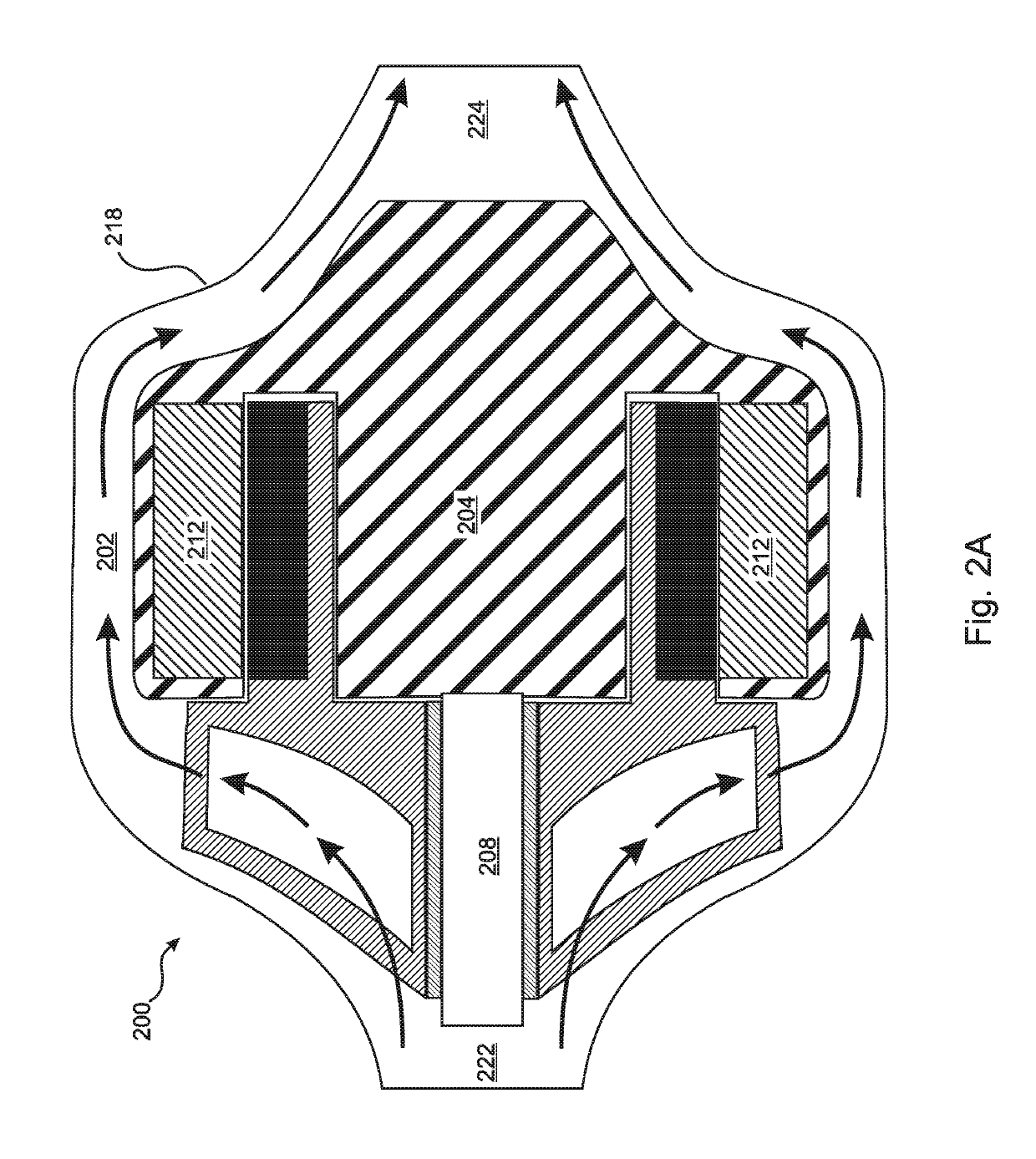
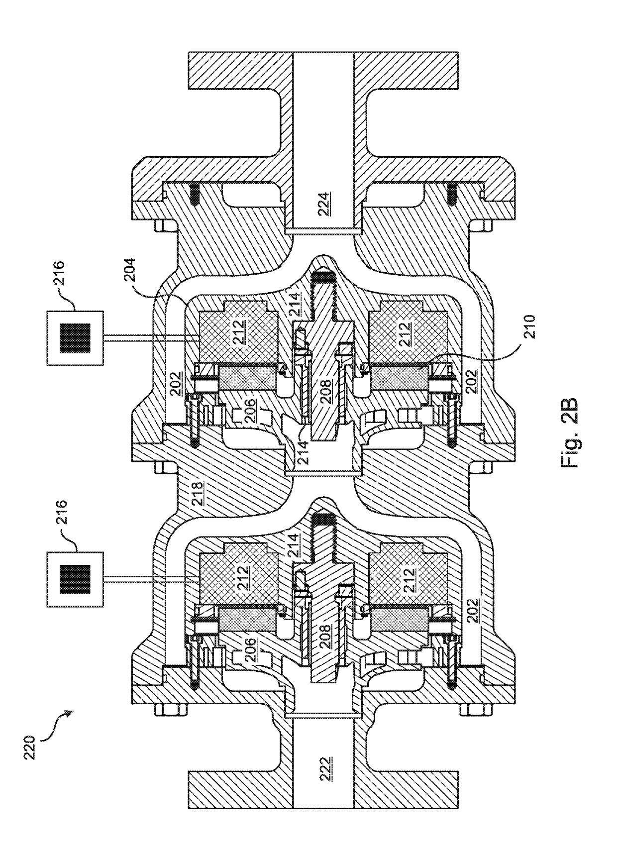
[0049]The present invention is an integral motor pump or pump module that is configured to direct the discharge of process fluid from a rotor over the surface of the integral motor housing, thereby reducing or eliminating any need for a separate, dedicated motor cooling flow path. For example, in the embodiment of FIG. 2A, the discharge 202 from the rotor 206 is directed to pass over and around the motor housing 204 of the module, so that the motor 212 is directly cooled by the discharge of the impellor 206, and does not require a separate, dedicated cooling fluid path.

[0050]In embodiments, more than 80% of the fluid that enters the module inlet 222 is directed through the discharge path 202 to the module outlet 224, and at least 20% of the motor housing 204 is in direct contact with the discharge path 202. In embodiments, more than 90% of the fluid that enters the module 200 flows from the inlet 222 to the outlet 224 through the discharge path 202 and at least 50% of the motor hous...


PUM


Abstract

An integral motor pump module directs at least 90% of its rotor discharge over at least 50% of its motor housing surface, thereby cooling the motor with little or no need for a separate flow path. The discharge can flow through an annulus formed between the motor and pump housings, and can extend over substantially all of the sides and rear of the motor housing. The rotor can be fixed to a rotating shaft, or rotate about a fixed shaft, which can be threaded into the motor and / or module housing. A plurality of the modules can be combined into a multi-stage pump, with rotor speeds independently controlled by corresponding variable frequency drives. The motor can be a radial or axial permanent magnet or induction motor. A separate cooling flow can provide additional cooling e.g. when pumping heated process fluids. Embodiments include guide vanes and / or diffusers.

Description

FIELD OF THE INVENTION[0001]The invention relates to pumps, and more particularly, to integral sealed motor pumps.BACKGROUND OF THE INVENTION[0002]In a conventional rotodynamic pump design, fluid flow and pressure are generated by an impeller rotating inside a stationary pump casing. The torque required to drive the rotor is provided by an external driver and transmitted through a rotating shaft to the impeller. Higher pressures can be achieved by adding multiple impeller stages in series and using a larger driver to provide torque to all stages through the same shaft. The shaft must get larger in diameter and longer in length to accommodate the combined torque and axial length of all rotor stages. Pumps with high stage counts or a vertical arrangement can use very long shafts that lead to various rotordynamic issues related to shaft deflections and critical speeds. Furthermore, dynamic seals are required to maintain the pressure boundary at the locations where the rotating shaft pe...

Claims


Application Information

Patent Timeline
Patent Type & Authority Applications(United States)
IPC IPC(8): F04D29/44F04D1/04F04D1/06F04D13/06F04D29/22F04D29/42
CPCF04D29/447F04D1/04F04D1/06F04D13/0613F04D29/2272F04D29/4293F04D13/0633F04D29/669H02K16/005H02K16/02F04D1/066F04D13/0606F04D13/0666F04D13/14F04D29/5806H02K21/24H02K5/12H02K7/14H02K16/00H02K5/20
Inventor JUDGE, SCOTTDREISS, ANDREASHAVRILLA, NEILOLEXSON, DAVID
Owner FLOWSERVE MANAGEMENT CO
Why Eureka
Try Eureka