Optical polarizing filter

A technology of polarization and polarized optics, applied in the field of optical polarization filters, can solve problems such as interference with NIR light

Active Publication Date: 2018-08-21
VIAVI SOLUTIONS INC
View PDF2 Cites 10 Cited by
  • Summary
  • Abstract
  • Description
  • Claims
  • Application Information

AI Technical Summary

Problems solved by technology

However, ambient light may interfere with the NIR light during transmission to the user and / or during reflection from the user to the optical receiver

Method used


Image

  • Optical polarizing filter
  • Optical polarizing filter
  • Optical polarizing filter

Examples


Embodiment Construction

[0010] The following detailed description of example embodiments refers to the accompanying drawings. The same reference numbers in different drawings may identify the same or similar elements. As used herein, the terms "substantially", "approximately" and "about" mean a range of values ​​within + / -5% of the stated value.

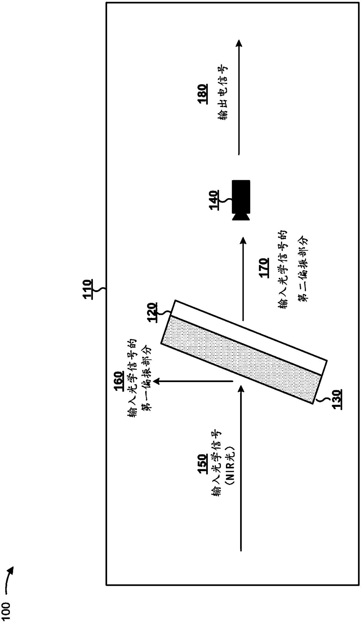
[0011] The optical receiver can receive light from a light source such as an optical transmitter. For example, the optical receiver may receive near infrared (NIR) light from the optical transmitter and reflected from a target such as a user or an object. In this case, the optical receiver can receive NIR light as well as ambient light, such as visible spectrum light. Ambient light can reduce the accuracy of determinations related to NIR light. For example, in a gesture recognition system, ambient light can reduce the accuracy of generating a three-dimensional image of a target based on NIR light. Therefore, the optical receiver may be optically coupled to...


PUM

PropertyMeasurementUnit
angle of incidenceaaaaaaaaaa
refractive indexaaaaaaaaaa

Abstract

An optical filter may include a substrate. The optical filter may include a set of alternating high refractive index layers and low refractive index layers disposed onto the substrate to polarizationbeam split incident light. The set of alternating high refractive index layers and low refractive index may layers may be disposed such that a first polarization of the incident light with a spectralrange of less than approximately 800 nanometers (nm) is reflected by the optical filter and a second polarization of the incident light with a spectral range of greater than approximately 800 nm is passed through by the optical filter. The high refractive index layers may be hydrogenated silicon (Si:H). The low refractive index layers may be silicon dioxide (SiO2).

Description

Background technique [0001] In some cases, it may be desirable to block certain wavelengths of energy and / or only transmit certain wavelengths of energy to the detector. For example, some detectors may be sensitive to certain wavelengths of energy. In one example, the optical transmitter may emit light that is ultimately received by the optical receiver. For example, in a gesture recognition system, the optical transmitter may emit near infrared (NIR) light to the user, and the NIR light may be reflected from the user to the optical receiver. In this case, the optical receiver can capture information about NIR light, and this information can be used to identify the gesture that the user is performing. For example, the device can use this information to generate a three-dimensional representation of the user, and based on the three-dimensional representation, recognize the gesture that the user is performing. However, during transmission of NIR light to the user and / or during ...

Claims


Application Information

Patent Timeline
Patent Type & Authority Applications(China)
IPC IPC(8): G02B5/30G02B5/20G02B27/28
CPCG02B5/20G02B5/30G02B27/283G02B5/28G02B5/3066G02B5/3041G02B5/281G02B5/3083G02B1/10H04B10/40
Inventor K.D.亨德里克斯S.罗兰兹
Owner VIAVI SOLUTIONS INC
Why Eureka
Try Eureka