Processing center coordinate system setting method

A machining center and coordinate system technology, applied in general control systems, control/adjustment systems, instruments, etc., can solve the problems of increasing the difficulty of debugging and low efficiency, and achieve the effects of intuitive and clear dimensional relationships, improved efficiency, and simplified times.

Inactive Publication Date: 2018-08-21
SUZHOU VERY PRECISION MACHINERY CO LTD
View PDF2 Cites 0 Cited by
  • Summary
  • Abstract
  • Description
  • Claims
  • Application Information

AI Technical Summary

Problems solved by technology

This method of setting the coordinate system is not only inefficient, but it is also easy to make mistakes in modifying the coordinate system during the debugging process, which increases the difficulty of debugging.

Method used


Image

  • Processing center coordinate system setting method
  • Processing center coordinate system setting method

Examples


Embodiment

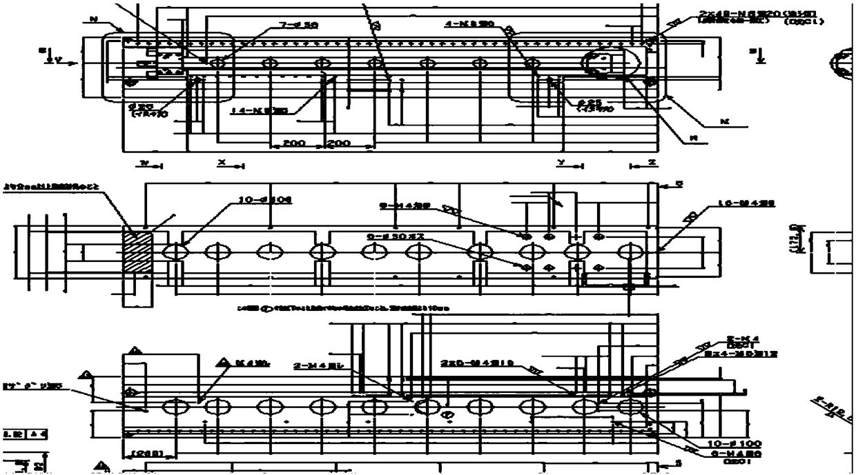
[0013] Example: such as figure 1 As shown, in the process of processing an aluminum product, the method of setting the coordinate system of the machining center is introduced. The same coordinate system is used for 5-face machining, which coincides with the marking datum, and the size relationship is intuitive and clear. At the same time, it simplifies the number of times to set the coordinate system and improves work efficiency. Since the dimensions of each processing surface are interrelated, there is no need to consider the impact on other processing surfaces when modifying the coordinate system, which reduces the workload of debugging engineers and technicians.

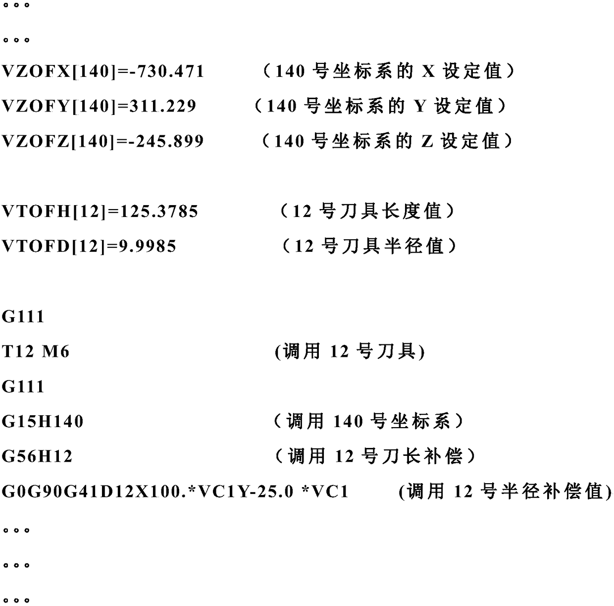
[0014] In the process of making the program, a macro program is introduced to set the tool length, radius value, coordinate system and other related processing parameters through the macro program. Taking the OKUMA OSP-P200-R system machine tool for debugging aluminum products in our company as an example,

[001...

specific example

[0019] Specific examples (partial procedures) are as follows

[0020]

[0021] After the processing program is debugged by engineers and technicians, set the relevant coordinate system, tool length, radius and other parameters in the program, and then close the program editing function through the key button on the machine panel. At this time, the processing program and The correctness of processing parameters. Completely avoid errors caused by human factors.


PUM


Abstract

The invention discloses a processing center coordinate system setting method. A plurality of faces to be processed of a workpiece are arranged in one coordinate system. The method of the invention introduces common coordinate system management. The invention is advantageous in that the multiple-face processing uses the same coordinate system, and superposes with labeling standard, and thereby thesize relation is obvious, and the times of setting the coordinate system is reduced, and efficiency is improved; as sizes of different processing faces are mutually related, the influence to other processing faces when the coordinate system is revised does not need to be considered, and thereby the work load for debugging workers can be decreased.

Description

technical field [0001] The invention relates to a machining center programming method, in particular to a machining center coordinate system setting method. Background technique [0002] In the programming process of vertical machining center, horizontal machining center and gantry machining center with four-axis function, it is inevitable to process multiple machining surfaces. The common way to set the coordinate system is to set the processing coordinate system on the relevant processing plane. If there are several processing planes, several processing coordinate systems need to be set. Taking the gantry machining center as an example, 5 machining coordinate systems need to be set for 5 surface machining, which are generally set on the relevant machining surfaces. Since there is no correlation between the processing coordinate systems, when it is necessary to modify the dimensions associated with other processing surfaces, a chain reaction may occur and other coordinate ...

Claims


Application Information

Patent Timeline
IPC IPC(8): G05B19/4093
CPCG05B19/4093G05B2219/35258
Inventor 马千里牛新征杨晓辉
Owner SUZHOU VERY PRECISION MACHINERY CO LTD
Why Eureka
Try Eureka