Full-data measurement path planning method foraero-engine blade

An aero-engine and measurement path technology, applied in mechanical measurement devices, measurement devices, and mechanical devices, etc., can solve the problems of high engine failure rate, affecting the working performance and service life of the whole machine, and reduce the number of measurements and redundancy. The effect of remaining data volume and rapid measurement

Inactive Publication Date: 2021-10-01
XI AN JIAOTONG UNIV
View PDF5 Cites 0 Cited by
  • Summary
  • Abstract
  • Description
  • Claims
  • Application Information

AI Technical Summary

Problems solved by technology

Due to the heavy working load and harsh working environment, the blade has always been a component with a high failure rate in the engine, which seriously affects the working performance and service life of the whole machine

Method used


Image

  • Full-data measurement path planning method foraero-engine blade
  • Full-data measurement path planning method foraero-engine blade
  • Full-data measurement path planning method foraero-engine blade

Examples


Embodiment

[0064] (1) Determine the sensor clamping method

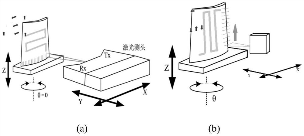
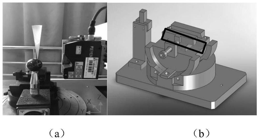
[0065] Respectively, the beam direction is parallel to the Z axis (such as figure 2 a) and the beam direction is perpendicular to the Z axis (as figure 2 Shown in b) The blade profile data is collected under two clamping methods. Taking the four-stage blade of a certain type of aero-engine compressor as a measurement example, the obtained measurement results are as follows Image 6 shown. Through the analysis of the collected data, the figure 2 The original data measured by method a have less data on the leading and trailing edges of the blade and the edges are not neat enough, which is not conducive to the subsequent point cloud data processing. Depend on figure 2 The point cloud data obtained by method b obtains a large number of data points on the front and rear edges of the blade, and has relatively neat boundary information, which can obtain better data processing effects.

[0066] (2) Path planning for blade pro...


PUM


Abstract

The invention discloses a full-data measurement path planning method for an aero-engine blade. The method comprises the following steps: determining a clamping mode of a sensor; installing the sensor according to the clamping mode of the sensor, selecting -30 degrees, -15 degrees, 0 degree, 15 degrees, 30 degrees, 150 degrees, 165 degrees, 180 degrees, 195 degrees and 210 degrees to measure the blade to obtain scanning data, and planning a measurement path of blade profile data; and optimizing the planned measurement path, and realizing full-data measurement of the blade profile. According to the invention, the clamping mode of the laser line scanning sensor and design of the measurement path are utilized, so that measurement of the blade molded surface data blade basin and blade back part is realized, measurement of front and rear edge data is also realized, and complete data of the blade molded surface is obtained. In addition, through an optimization strategy of an experiment path, rapid measurement of blade profile data is realized.

Description

technical field [0001] The invention belongs to the technical field of profile size detection of blades, and in particular relates to a path planning method for full data measurement of aeroengine blades. Background technique [0002] Since the industrial revolution, the rapid development of the manufacturing industry has gradually become the main factor promoting the process of industrialization. The power unit is the heart of mechanical equipment in the manufacturing industry, and it is of great significance to the durability and stability of the whole machine. As the core component of an aero-engine, blades are subject to very harsh working conditions and may be continuously eroded by creep damage, wet steam corrosion, and solid particle wear during operation. At the same time, in the case of high-speed rotation of the impeller machinery, the stress situation is complicated, and it may bear the centrifugal tensile stress generated during the operation of the equipment, t...

Claims


Application Information

Patent Timeline
Patent Type & Authority Applications(China)
IPC IPC(8): G01B11/00G01B11/24
CPCG01B11/00G01B11/24G01B5/003
Inventor 李兵辛美婷魏翔李磊
Owner XI AN JIAOTONG UNIV
Why Eureka
Try Eureka