
Dead zone compensation method for H-bridge topology

A technology of dead zone compensation and topology, applied in the direction of output power conversion devices, electrical components, etc., can solve problems affecting the output quality of the circuit, power switch tube through damage, output voltage fundamental wave error, etc., to increase the output voltage, reduce the The influence of small odd harmonics and the effect of increasing costs

Active Publication Date: 2018-08-21
爱士惟科技股份有限公司
View PDF4 Cites 1 Cited by
  • Summary
  • Abstract
  • Description
  • Claims
  • Application Information

AI Technical Summary

Problems solved by technology

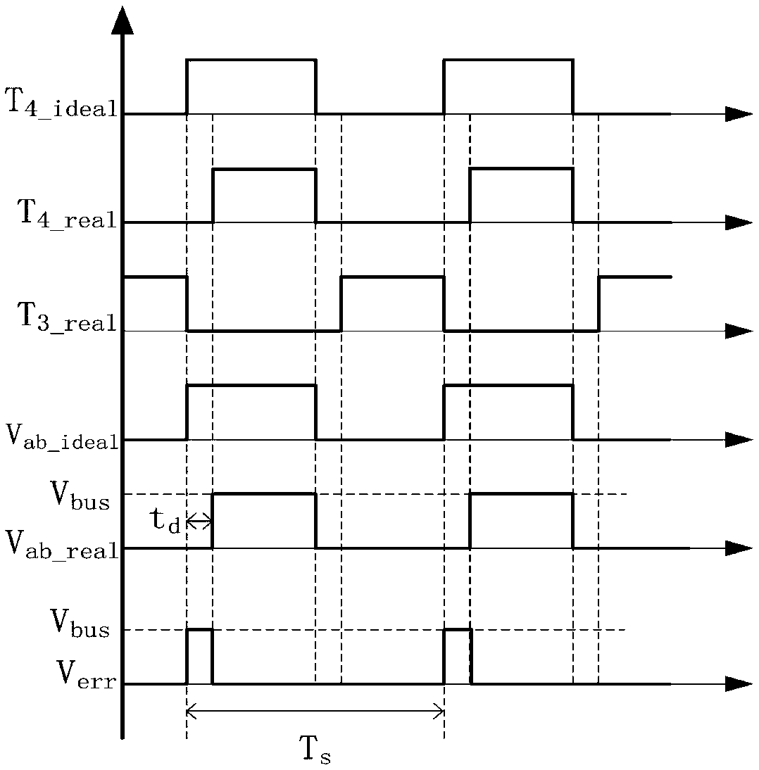
[0012] In addition to the fundamental wave error of the output voltage, this error voltage also generates odd harmonics. Therefore, when the PWM control is used, the dead zone control is added. Although the problem of direct damage to the power switch tube of the same bridge arm is solved, it is also Bring in the fundamental wave error of the output voltage, generate odd harmonics of the current, and affect the output quality of the circuit

Method used


Image

  • Dead zone compensation method for H-bridge topology
  • Dead zone compensation method for H-bridge topology
  • Dead zone compensation method for H-bridge topology

Examples


Embodiment Construction

[0049] The preferred embodiments of the present invention will be described in detail below in conjunction with the accompanying drawings, so that the advantages and features of the present invention can be more easily understood by those skilled in the art. It should be noted here that the descriptions of these embodiments are used to help understand the present invention, but are not intended to limit the present invention. In addition, the technical features involved in the various embodiments of the present invention described below may be combined with each other as long as they do not constitute a conflict with each other.

[0050] This embodiment provides a dead zone compensation method of H-bridge topology, the flow chart of which is as follows Figure 4, the specific implementation process is as follows:

[0051] S1, analyze all operating modes of the H-bridge topology circuit under the corresponding modulation mode, the modulation mode includes unipolar SPWM modulat...


PUM


Abstract

The invention discloses a dead zone compensation method for H-bridge topology. With the method adopted, the influence of odd-order harmonics brought by dead zone control can be decreased when the deadzone control is carried out, and output quality is improved. The method includes the following steps that: A, all working modes of an H-bridge topology circuit in corresponding modulation modes are analyzed; B, the average error voltage of the H-bridge topology circuit in each working mode is calculated; C, the current working mode of the H-bridge topology circuit is judged; D, an average error voltage corresponding to the current working mode of the H-bridge topology circuit which is judged in the step C is selected from the average error voltages calculated in the step B; and E, the averageerror voltage selected in the step D is converted to a PWM duty cycle compensation amount, and the PWM duty cycle compensation amount is superimposed on the original PWM duty cycle reference of the current H-bridge topology circuit.

Description

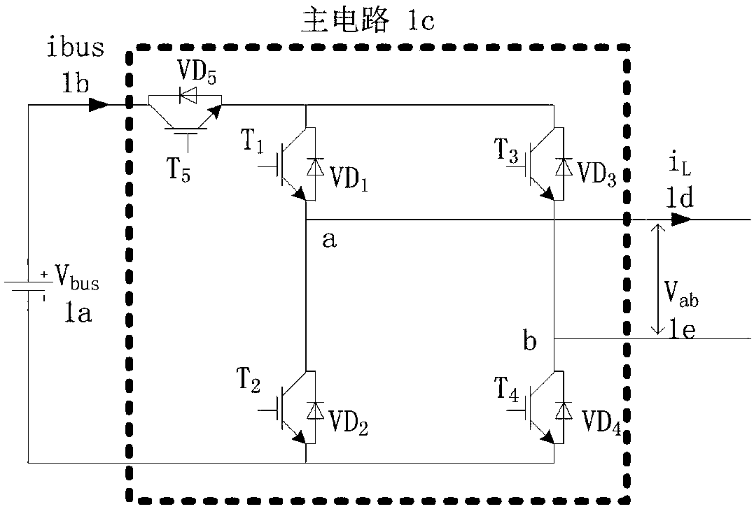
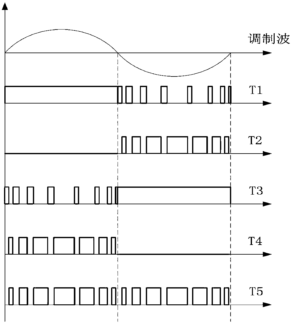
technical field [0001] The invention relates to the field of grid-connected inverters, and in particular relates to a dead-zone compensation method of an H-bridge topology. Background technique [0002] In the current power conversion and power drive industries, the H-bridge topology grid-connected inverter is widely used as a classic topology. Among them, the H-bridge topology includes classic H4 bridge, H5 bridge, multi-level H bridge and so on. For example, H5 bridge topology grid-connected inverter, such as figure 1 As shown, the main circuit is driven by unipolar SPWM, figure 1 in, V bus is the DC bus voltage; T 1 to T 5 It is the switching tube of H5 topology; VD 1 to VD 5 Respectively are the parasitic diode of the switching tube; V ab The output voltage of the main circuit. To allow the exchange of reactive components, figure 1 The drive waveform of the H5 bridge topology grid-connected inverter is shown as figure 2 As shown, the following three principle...

Claims


Application Information

Patent Timeline
Patent Type & Authority Applications(China)
IPC IPC(8): H02M1/38
CPCH02M1/38H02M1/385
Inventor 姚佳雨李小龙郭文武舒成维程进
Owner 爱士惟科技股份有限公司
Learn More