Electromagnetic pulse forming device of plate type part and forming method thereof

An electromagnetic pulse and parts technology, applied in the field of electromagnetic pulse forming devices, can solve the problems of affecting the forming accuracy, limiting the forming height of the sheet metal, and scratches on the surface of the sheet metal, so as to improve the utilization rate of discharge energy, increase the forming limit, and improve the forming The effect of precision

Active Publication Date: 2018-08-24
CENT SOUTH UNIV
View PDF11 Cites 8 Cited by
  • Summary
  • Abstract
  • Description
  • Claims
  • Application Information

AI Technical Summary

Problems solved by technology

However, in the process of single-point incremental forming, there are also the following disadvantages: (1) The contact area between the tool head and the sheet is small, and the surrounding materials of the tool head are difficult to flow, so that the sheet shows an overall thinning and deformation process, which limits the forming of the sheet Height; (2) The size of the tool head is small and the rigidity is poor, which is difficult to be suitable for the precise forming of high-hardness and large-thickness sheets; (3) There are obvious scratches on the surface of the sheet, and the sheet forming accuracy is poor
Moreover, in the above-mentioned patents and papers, multiple oil cylinders are used to stretch the sheet metal, but in actual use, the movements of multiple oil cylinders tend to be out of sync.
When the size of the sheet is larger, this out-of-synchronization will cause the sheet to be more inclined after being drawn, which will eventually affect the forming accuracy

Method used


Image

  • Electromagnetic pulse forming device of plate type part and forming method thereof
  • Electromagnetic pulse forming device of plate type part and forming method thereof
  • Electromagnetic pulse forming device of plate type part and forming method thereof

Examples


Embodiment Construction

[0039] In order to facilitate the understanding of the present invention, the present invention will be described more fully and in detail below in conjunction with the accompanying drawings and preferred embodiments, but the protection scope of the present invention is not limited to the following specific embodiments.

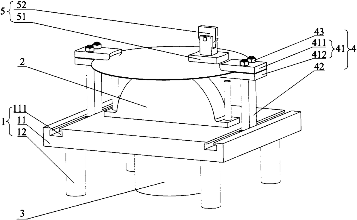
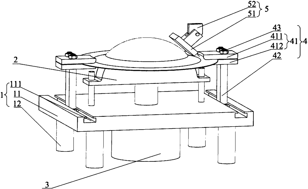
[0040] Such as Figure 1 to Figure 4 As shown, an electromagnetic pulse forming device for plate-shaped parts includes a support frame 1, a punch 2, a lifting mechanism 3, a clamping mechanism 4, and an electromagnetic pulse element 5. The punch 2 is installed on the support frame 1, and the lifting mechanism 3 The top of the top is connected with the bottom of the punch 2. There are two clamping mechanisms 4, which are symmetrically distributed on both sides of the punch 2. The top of the clamping mechanism 4 is provided with a clamping element 41, and the electromagnetic pulse element 5 is located on the convex mold. Above the die 2, there is a gap between ...


PUM


Abstract

The invention discloses an electromagnetic pulse forming device of a plate type part. The electromagnetic pulse forming device comprises a supporting frame, a male die, a lifting mechanism, clamping mechanisms and an electromagnetic pulse element, wherein the male die is arranged on the supporting frame, the upper portion of the lifting mechanism is connected with the lower portion of the male die, the number of the clamping mechanisms is two, the clamping mechanisms are symmetrically distributed on the two sides of the male die respectively, clamping elements are arranged at the top ends of the clamping mechanisms, the electromagnetic pulse element is located above the male die, a gap is formed between the electromagnetic pulse element and the male die, and the gap is used for containingplate materials to be formed. The invention further provides a forming method adopting the same. The electromagnetic pulse forming device can effectively reduce the size of the die, is beneficial to reducing the manufacturing cost of the die, and high in forming precision and facilitates accurate forming of large-size plate materials.

Description

technical field [0001] The invention relates to the field of plastic forming of materials, in particular to an electromagnetic pulse forming device for plate-shaped parts and a forming method thereof. Background technique [0002] With the rapid development of high-tech industries such as aerospace, there is an urgent need to use large-scale plate-shaped parts with very significant structural benefits in advanced aircraft, spacecraft, rockets, and missiles to reduce weight, improve the load-carrying capacity limit and range of the carrier, etc. performance. Parts with large size, thin wall, light weight, high precision, high strength, and good fatigue resistance are typical representatives. For example: large storage tank heads of spacecraft, cabin sections of cruise missiles, aircraft and spacecraft hoods, auxiliary fuel tanks and engine casings, etc. [0003] The plastic forming methods of large-size plate-shaped parts mainly include: (1) Using giant presses for strong m...

Claims


Application Information

Patent Timeline
Patent Type & Authority Applications(China)
IPC IPC(8): B21D26/14B21D43/00B21D37/10B21D31/00
Inventor 崔晓辉张志武喻海良
Owner CENT SOUTH UNIV
Why Eureka
Try Eureka