A self-locking nut closing device

A technology of self-locking nut and closing device, which is applied to nuts, threaded fasteners, connecting components, etc., to achieve the effect of convenient operation, simple structure design and solving the problem of closing

Active Publication Date: 2020-07-10
河南航天精工制造有限公司
View PDF1 Cites 0 Cited by
  • Summary
  • Abstract
  • Description
  • Claims
  • Application Information

AI Technical Summary

Problems solved by technology

[0005] The purpose of the present invention is to provide a self-locking nut closing device that can realize the closing operation without disassembling the self-locking nut, which is used to solve the technology in the prior art that the self-locking nut must be disassembled to perform the closing operation question

Method used


Image

  • A self-locking nut closing device
  • A self-locking nut closing device
  • A self-locking nut closing device

Examples


specific Embodiment 1

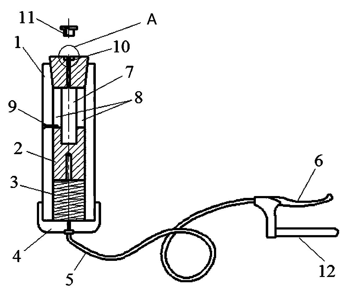
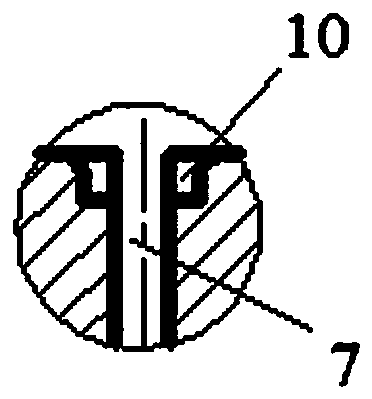
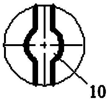
[0027] Such as Figure 1~3 As shown, the self-locking nut closing device is mainly composed of a mold base 1, a closing mold assembly 2, a spring 3, a blocking cover 4, a flexible shaft 5 and a handle. The mold base 1 is a hollow cylinder, and the closing mold assembly 2 and the spring 3 are arranged in the inner cavity of the mold base 1 . The closing die assembly 2 includes a clamping die, a connecting arm and a mounting seat. In this embodiment, there are two clamping dies, and the clamping die, connecting arm and mounting seat are integrated to form the closing die assembly 2 . The closing mold assembly 2 is arranged with a convex-shaped through-groove 7, the groove walls on both sides of the convex-shaped through-groove 7 are closer to form clamping molds, and the groove walls on both sides of the convex-shaped through-groove 7 are farther away. Connecting arm, the groove bottom position of convex-shaped through groove 7 forms mounting seat, and the clamping mold of clos...

Embodiment 2

[0030] Embodiment 2 of the present invention differs from Embodiment 1 in that: the stop structure adopts the internal structure of the telescopic rod, and by setting a convex portion on the outer peripheral surface of the clamping mold, the convex portion can be ring-shaped or a single convex portion Block, the inner side wall of the mold base is provided with an annular stepped convex part matching with the convex part on the clamping mold, and the convex part on the clamping mold and the convex part on the mold base block each other, thereby limiting the displacement of the clamping mold.

Embodiment 3

[0031] Embodiment 3 of the present invention differs from Embodiment 1 in that: the flexible shaft of the closing drive part is in the form of a telescopic rod, the inner rod of the telescopic rod is connected with the clamping mold, and the sleeve of the telescopic rod is fixed on the blocking cover. The sleeve is fixed to the fixed handle, and the inner rod is fixed to the moving handle. The retraction of the telescopic rod is realized by squeezing the moving handle, thereby realizing the axial displacement of the clamping mold.


PUM


Abstract

The invention relates to a self-locking nut closing device. The self-locking nut closing device comprises a die holder. The front end, facing a self-locking nut, of the die holder is movably providedwith a closing die assembly in the front and back direction. The closing die assembly comprises at least two clamping dies which are evenly distributed in the circumferential direction. The opposite inner sides of the front ends of the clamping dies are provided with closing die cavities for containing the self-locking nut. The closing device further comprises a drive mechanism used for driving the closing die assembly to do reciprocating motion. Conical surface cooperating structures are arranged between the die holder and the clamping dies and are used for guiding the clamping dies to extrude and get close to each other when the closing die assembly moves backwards so that the clamping dies can carry out extruding and closing operation on the self-lock nut in the closing die cavity. Theself-lock nut closing device is mainly used for carrying out secondary closing on a nut fixed to a related component, and the nut does not need to be dismounted from the related component. The self-locking nut closing device is simple in structural design, convenient to operate and capable of effectively solving the closing problem of the fixed nut.

Description

technical field [0001] The invention relates to a self-locking nut closing device. Background technique [0002] In the field of aerospace, self-locking nuts are widely used as a common fastener. The self-locking nut mainly relies on the closure to ensure its locking torque and realize its anti-loosening and anti-vibration functions. Commonly used closing molds are generally divided into an upper mold and a lower mold, and the self-locking nut is closed by closing the upper and lower molds. [0003] The authorized announcement number is CN205587564U, and the Chinese invention patent titled a self-locking nut closing device discloses a self-locking nut closing device. The device is composed of an upper die and a lower die. The mold is provided with a matching pin matching the closing die, and the self-locking nut is inserted on the matching pin, and then the closing is completed under the action of the closing die. [0004] The above-mentioned self-locking nut closing devi...

Claims


Application Information

Patent Timeline
Patent Type & Authority Patents(China)
IPC IPC(8): B21D53/24B21K1/70
CPCB21D53/24B21K1/707
Inventor 连实慧李祥军胡庆宽关悦石大鹏
Owner 河南航天精工制造有限公司
Why Eureka
Try Eureka