Workpiece positioning device of three-dimensional laser cutting device

A cutting equipment, three-dimensional laser technology, applied in laser welding equipment, welding equipment, metal processing equipment and other directions, can solve problems such as difficulty in ensuring workpiece cutting accuracy, hidden dangers in production safety, and low production efficiency

Inactive Publication Date: 2018-08-24
JIANGSU LIDIAN MACHINE TOOL TECH CO LTD
View PDF5 Cites 0 Cited by
  • Summary
  • Abstract
  • Description
  • Claims
  • Application Information

AI Technical Summary

Problems solved by technology

[0003] The existing three-dimensional laser cutting equipment generally hangs the robot on the gantry, and sets a bracket under the robot. The workpiece is placed on the bracket during the cutting operation. Due to the lack of a reliable workpiece positioning mechanism, it is difficult to ensure the cutting accuracy of the workpiece; and the workpiece The unloading and unloading operation is done manually in the robot work area, which has hidden dangers in production safety; in addition, the existing 3D laser cutting equipment must stop the robot during the loading and unloading process of the workpiece, resulting in low production efficiency and waste of equipment resources. adverse consequences of

Method used


Image

  • Workpiece positioning device of three-dimensional laser cutting device
  • Workpiece positioning device of three-dimensional laser cutting device
  • Workpiece positioning device of three-dimensional laser cutting device

Examples


Embodiment Construction

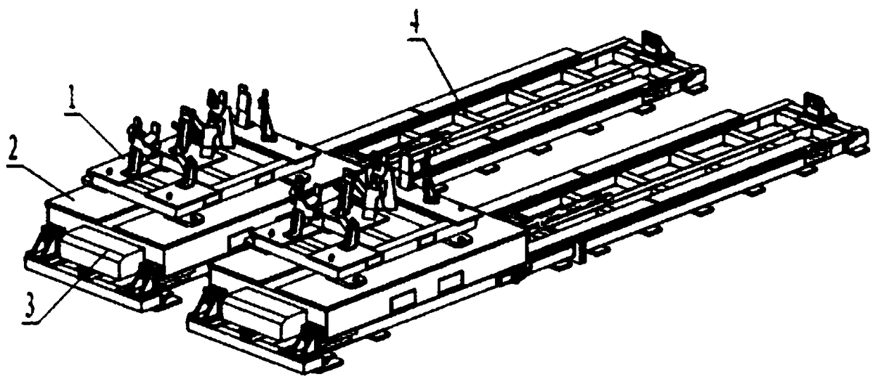
[0024] see figure 1 , the present invention includes two parts arranged left and right, wherein each part is composed of a combined fixture 1, a mobile vehicle body 2, a drive mechanism 3 and a base 4, the combined fixture 1 is installed on the mobile vehicle body 2, and the mobile vehicle body 2 is assembled with the base 4, and the driving mechanism 3 is installed between the mobile vehicle body 1 and the base 4.

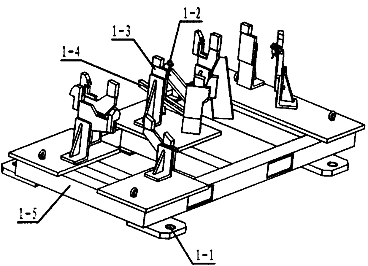
[0025] see figure 1 , figure 2 The combination fixture 1 of the present invention includes a fixture base 1-5, a workpiece connection support assembly 1-3 and a material receiving plate 1-4, the fixture base 1-5 is a hollow structure, and the workpiece connection support assembly 1-3 and the connection plate The material plate 1-4 is fixed on the fixture base 1-5, a proximity switch 1-2 is provided on the workpiece connection support assembly 1-3, positioning pin holes 1-1 are set at the four corners of the fixture base 1-5, and the combination The fixture 1 i...


PUM


Abstract

The invention relates to a workpiece positioning device of a three-dimensional laser cutting device. The workpiece positioning device of the three-dimensional laser cutting device is used for improving the cutting accuracy of the three-dimensional laser cutting device, and comprises two parts arranged on the left part and the right part, wherein each part is formed by a combined fixture, a mobilevehicle, a drive mechanism and a base; the combined fixture is arranged on the mobile vehicle; the mobile vehicle is assembled with the base; and the drive mechanism is arranged between the mobile vehicle and the base. According to the workpiece positioning device of the three-dimensional laser cutting device provided by the invention, the workpiece cutting accuracy is ensured, the production efficiency and the device utilization ratio are improved, the working conditions of operating personnel are improved, and the hidden dangers in safe production are eliminated.

Description

technical field [0001] The invention relates to a three-dimensional laser cutting device, in particular to a workpiece positioning device of the three-dimensional laser cutting device, belonging to the technical field of laser cutting. Background technique [0002] As a high-end product of laser application technology, three-dimensional laser cutting equipment has been widely used in the equipment manufacturing industry. It is an advanced cutting equipment that can perform multi-angle and multi-directional flexible cutting on metal sheets of different thicknesses. It uses industrial robots to flexibly And fast features, according to the shape and size programming of the cutting workpiece, the three-dimensional cutting of the workpiece is carried out through the laser cutting head. [0003] The existing three-dimensional laser cutting equipment generally hangs the robot on the gantry, and sets a bracket under the robot. The workpiece is placed on the bracket during the cuttin...

Claims


Application Information

Patent Timeline
Patent Type & Authority Applications(China)
IPC IPC(8): B23K26/38B23K26/70
CPCB23K26/38B23K26/70B23K26/702
Inventor 徐成
Owner JIANGSU LIDIAN MACHINE TOOL TECH CO LTD
Why Eureka
Try Eureka