Quickly assembled chuck

A fast, driving device technology, applied in the field of tooling and fixtures, can solve the problems of low carrier installation efficiency, low product processing accuracy, and reduced positioning accuracy, and achieve the effects of convenient processing and manufacturing, fast clamping and positioning speed, and reduced positioning costs

Pending Publication Date: 2018-08-24
昆山冠品优精密机械有限公司
View PDF0 Cites 0 Cited by
  • Summary
  • Abstract
  • Description
  • Claims
  • Application Information

AI Technical Summary

Problems solved by technology

[0002] Products with small size and high machining accuracy are generally installed on the carrier first, and then the carrier is installed on the processing machine tool by means of screws. The carrier installation efficiency is low, and the positioning accuracy after installation is low. Long-term use After wear, the positioning accuracy will be reduced, resulting in low processing accuracy of the product. At present, there is also a structure that achieves rapid positioning through cylindrical pins on the carrier and the workbench of the extra bed, and then tightens and fixes it through the connecting piece. However, if this structure is cylindrical If the gap between the pin and the pin hole is large, the carrier will shake on the horizontal plane. If the gap between the cylindrical pin and the pin hole is too small, it will be difficult to quickly clamp and use.

Method used


Image

  • Quickly assembled chuck
  • Quickly assembled chuck
  • Quickly assembled chuck

Examples


Embodiment

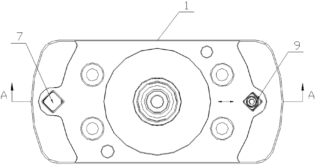
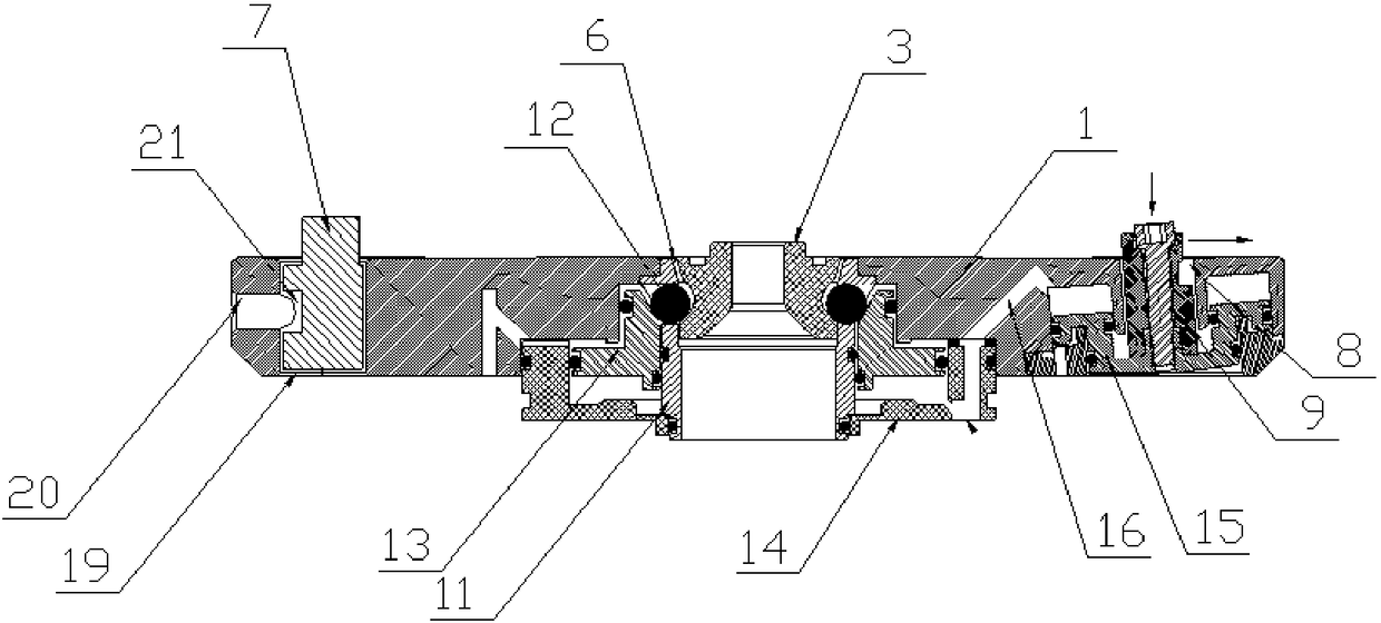
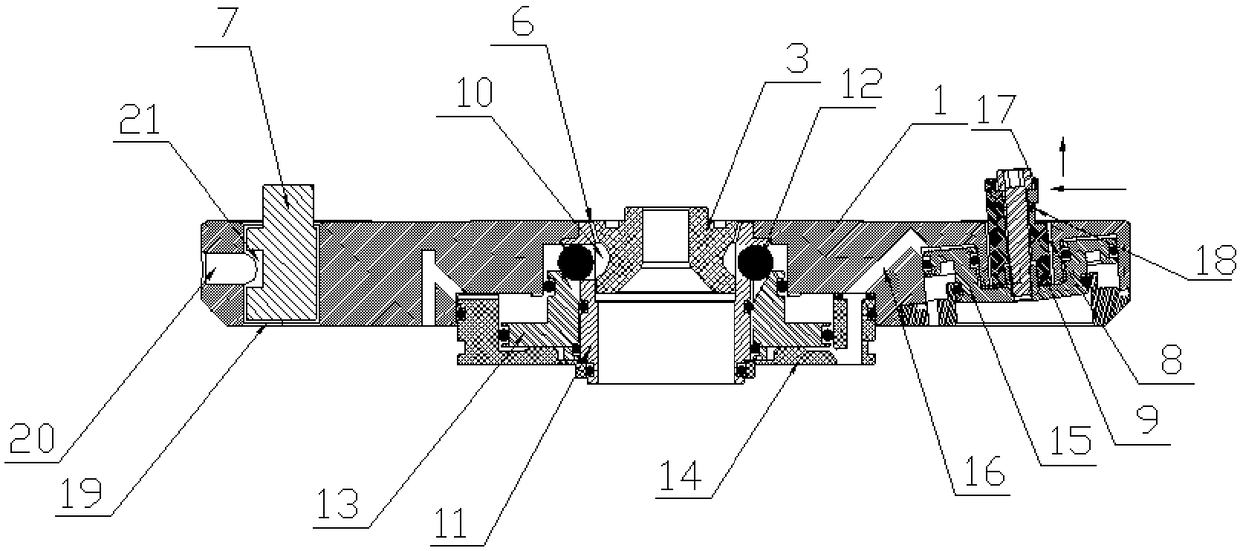
[0020] Embodiment: A quick clamping chuck, including a main body 1 and a carrier 2, the carrier 2 can be placed on the upper surface of the main body 1, and the lower surface of the carrier 2 is fixed with a pull stud 3. The carrier 2 is also provided with a first pin hole 4 and a second pin hole 5 with a non-circular cross-section extending in the vertical direction, and a vertically extending pin hole is provided on the upper surface of the main body 1. Slot 6, the slot 6 is provided with a buckle structure and a buckle drive device, the pull stud 3 on the lower side of the carrier 2 can be inserted into the slot 6 of the main body 1 and along the vertical direction with the buckle structure The snap-fit ​​connection of the stop, the snap-in driving device can drive the snap-in structure in the slot 6 to snap-in or release with the upper pull stud 3 of the carrier 2, and the upper side of the main body 1 is also fixed with a non-circular cross-section The fixed pin 7 is inse...


PUM


Abstract

The invention discloses a quickly assembled chuck. The quickly assembled chuck comprises a main body and a carrier, wherein the carrier can be attached to the main body, and is fixedly provided with apop rivet; a first pin hole and a second pin hole are formed in the carrier, and cross sections of the first pin hole and the second pin hole are non-circular along a vertical direction; the main body is provided with a slot along a vertical direction; the pop rivet can be inserted in the slot and is connected with a buckle structure in the slot in a fastened manner; a buckle driving device can drive the buckle structure and the pop rivet to be fastened or unfastened; a fixing pin of which the cross section is non-circular is fixedly arranged on the main body; the fixing pin can be inserted in the first pin hole in a locking manner in a peripheral direction; an inclined hole buoyancy lifting pin is slidably inserted in an inclined hole in the main body, and can extend out of the inclinedhole by a certain height; the cross section of the upper end of the inclined hole buoyancy lifting pin has a non-circular structure; a buoyancy lifting pin driving device drives the inclined hole buoyancy lifting pin to slide; and the inclined hole buoyancy lifting pin can be inserted in the second pin hole in a locking manner in a peripheral direction. By the quickly assembled chuck, machining and manufacturing are facilitated, clamping and positioning speed is high, positioning is accurate, the positioning cost is reduced, and the machining efficiency is improved.

Description

technical field [0001] The invention relates to a tooling fixture, in particular to a quick clamping chuck suitable for high-precision product processing. Background technique [0002] Products with small size and high machining accuracy are generally installed on the carrier first, and then the carrier is installed on the processing machine tool by means of screws. The carrier installation efficiency is low, and the positioning accuracy after installation is low. Long-term use After wear, the positioning accuracy will be reduced, resulting in low processing accuracy of the product. At present, there is also a structure that achieves rapid positioning through cylindrical pins on the carrier and the workbench of the extra bed, and then tightens and fixes it through the connecting piece. However, if this structure is cylindrical If the gap between the pin and the pin hole is large, the carrier will shake on the horizontal plane. If the gap between the cylindrical pin and the p...

Claims


Application Information

Patent Timeline
Patent Type & Authority Applications(China)
IPC IPC(8): B23Q3/06
CPCB23Q3/06
Inventor 宇金龙
Owner 昆山冠品优精密机械有限公司
Why Eureka
Try Eureka