Camera and robot hand-eye calibration method based on ROS

A hand-eye calibration and robot technology, applied in the field of robot vision, can solve the problems of inconvenient use, prolonged visual experiment period, long time-consuming hand-eye calibration, etc., and achieves the effect of high degree of autonomy and strong expansibility

Inactive Publication Date: 2018-08-24
NANJING UNIV OF SCI & TECH
View PDF9 Cites 32 Cited by
  • Summary
  • Abstract
  • Description
  • Claims
  • Application Information

AI Technical Summary

Problems solved by technology

However, the general hand-eye calibration process is complicated and requires manual intervention, or taking marker points, or manually recording data, which is inconvenient to use. However, hand-eye calibration is often used in vision experiments, whether it is the position of the camera or the position of the robot arm. Or when the type of the robot arm changes, the hand-eye calibration must be performed again, while the traditional hand-eye calibration takes a long time, which greatly lengthens the cycle of the visual experiment

Method used


Image

  • Camera and robot hand-eye calibration method based on ROS
  • Camera and robot hand-eye calibration method based on ROS
  • Camera and robot hand-eye calibration method based on ROS

Examples


Embodiment

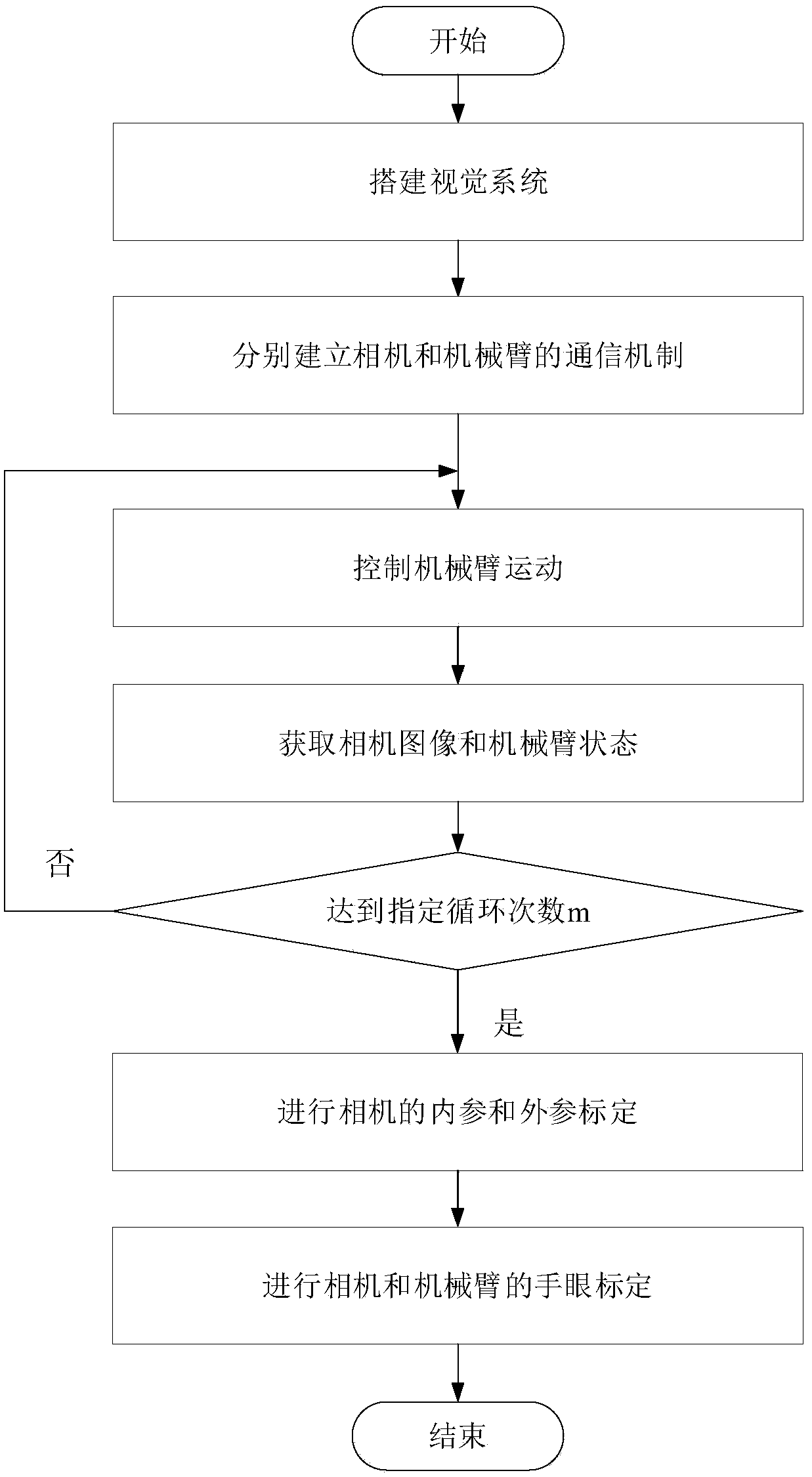
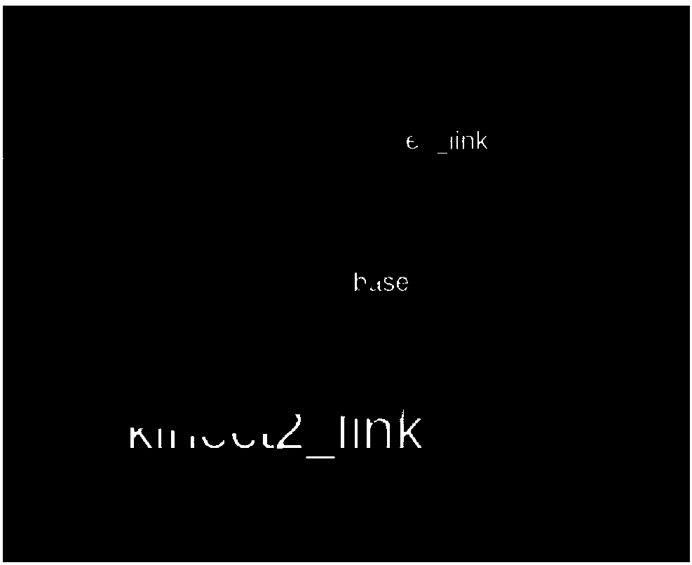
[0056] The ur3 robot arm and the kinect2 depth camera are used to construct the vision system, in which ur3 has 6 degrees of freedom (joints), kinect2 integrates RGB camera and Depth camera, kinect2 is installed in a fixed position outside the robot arm, considering the field of view and measuring range of kinect2 The distance range, the schematic diagram of the installation position of the kinect2 and ur3 robotic arms are as follows figure 2 Shown, and marked the RGB camera coordinate system O of kinect2 c , ur3 manipulator base coordinate system O r , where red, green and blue represent the x, y, and z axes respectively.

[0057] Use A4 paper to print the calibration board, select chess5x7x0.03 for the specification of the calibration board, such as figure 2 shown.

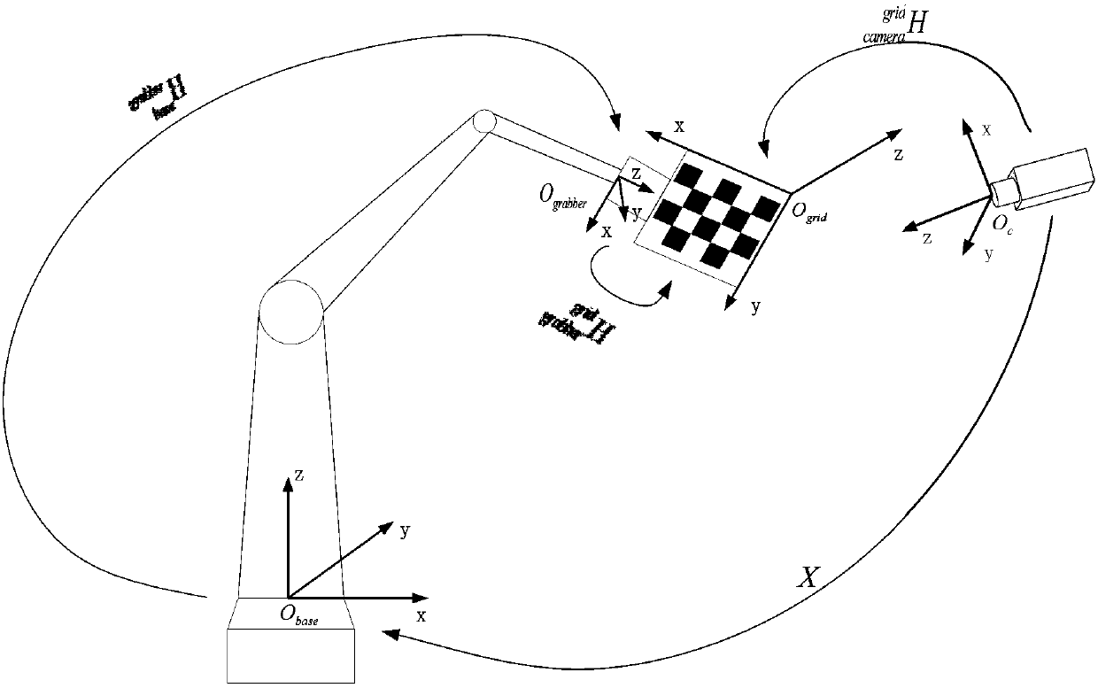
[0058] The relationship between the coordinate systems used in the whole calibration process is as follows: image 3 As shown, a total of 4 coordinate systems are involved: the base coordinate system of th...


PUM


Abstract

The invention discloses a camera and robot hand-eye calibration method based on an ROS. According to the camera and robot hand-eye calibration method based on the ROS, through setting up of a visual system, a mechanical arm and an operation object of the mechanical arm are within the view field of the camera; then, communication mechanisms between the camera and the ROS and between the mechanicalarm and the ROS are established, on one hand, motion control over the mechanical arm is achieved, on the other hand, the images of the camera and the state of the mechanical arm are obtained, and datacollection is conducted; calibration of internal reference and external reference of the camera is conducted, and parameters of the camera are obtained; and finally, according to different installation manners of the camera, hand-eye calibration of the camera and the mechanical arm is conducted, and a hand-eye calibration matrix is obtained. By the adoption of the camera and robot hand-eye calibration method based on the ROS, automatic hand-eye calibration of the camera and the mechanical arm is achieved, manual intervention is reduced, terminal commands are just called twice in the whole calibration process, the autonomous degree is high, the limitation of the type and number of the camera is avoided, the limitation of the type of mechanical arm is avoided, the expandability is high, itis just needed to print a piece of A4 checkerboard paper in the calibration process, no mark is needed, and the camera and robot hand-eye calibration method based on the ROS is convenient to perform and practical.

Description

technical field [0001] The invention relates to a robot vision method, in particular to a ROS-based camera and a robot hand-eye calibration method. Background technique [0002] With the development of computer technology, computer vision, as an important research field of artificial intelligence, has been widely used in various industries. Combining computer vision technology with robotics has also enabled the field of intelligent robotics to develop vigorously. For the grasping of the manipulator, the manual teaching method is traditionally used, such as breaking the manipulator by hand, so that the manipulator can go to a fixed position for grasping. This method is relatively inefficient and because the manipulator has no sense of the surrounding environment. , if the position of the robotic arm or the position of the object changes, the robotic arm cannot grasp the object. [0003] Applying computer vision to the field of robotics usually combines pattern recognition a...

Claims


Application Information

Patent Timeline
Patent Type & Authority Applications(China)
IPC IPC(8): B25J9/16
CPCB25J9/161B25J9/1692B25J9/1697
Inventor 郭毓陈宝存吴巍苏鹏飞饶志强吴禹均郭健吴益飞郭飞肖潇蔡梁
Owner NANJING UNIV OF SCI & TECH
Why Eureka
Try Eureka