A Spiral Microchannel Electrofluidic Nozzle

A micro-channel, electro-fluid technology, applied in printing and other directions, can solve the problems that the printing accuracy is difficult to meet the requirements, the solution is easy to block, etc., and achieve the effect of improving the liquid control accuracy, the liquid uniformity, and the printing efficiency.

Active Publication Date: 2019-10-25
HUAZHONG UNIV OF SCI & TECH
View PDF6 Cites 0 Cited by
  • Summary
  • Abstract
  • Description
  • Claims
  • Application Information

AI Technical Summary

Problems solved by technology

[0007] Aiming at the disadvantages that the printing accuracy of the needle-tube nozzle in the prior art is difficult to meet the requirements, and the solution is easy to block the nozzle, the present invention provides a spiral micro-channel electrofluid nozzle, which aims at Cooperate to form a spiral micro-channel, transfer the outlet of the flow channel from the inside of the needle tip to the outside of the needle tip, thereby eliminating the limitation of the size of the needle tip by the traditional needle tube structure, making the needle tip scale smaller than that of the traditional needle tube, and using the probe Cooperate with the outer cylinder to achieve radial positioning, ensure coaxiality, thereby improving printing accuracy; and because the spiral micro-channel is formed by the cooperation of the outer surface thread of the probe and the inner wall of the outer cylinder, it is easy to disassemble and clean, and there is no need to replace the probe frequently , thereby prolonging the service life

Method used


Image

  • A Spiral Microchannel Electrofluidic Nozzle
  • A Spiral Microchannel Electrofluidic Nozzle
  • A Spiral Microchannel Electrofluidic Nozzle

Examples


Embodiment Construction

[0044] In order to make the object, technical solution and advantages of the present invention clearer, the present invention will be further described in detail below in conjunction with the accompanying drawings and embodiments. It should be understood that the specific embodiments described here are only used to explain the present invention, not to limit the present invention. In addition, the technical features involved in the various embodiments of the present invention described below can be combined with each other as long as they do not constitute a conflict with each other.

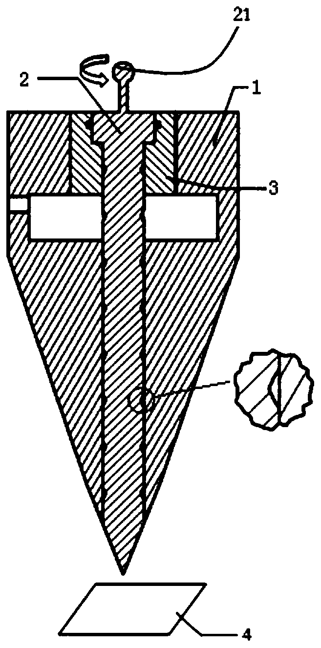
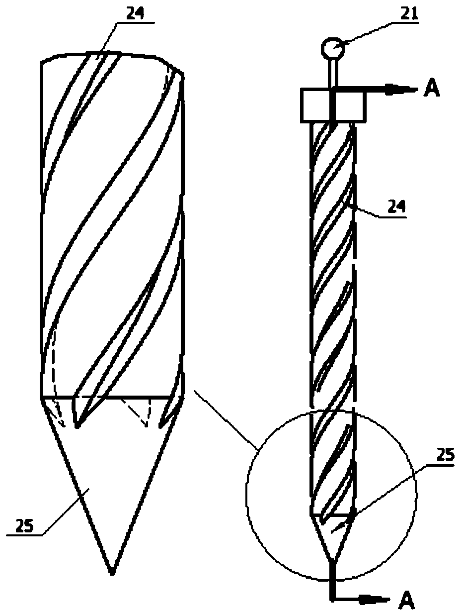
[0045] like Figure 1~5 Shown is the first embodiment of the present invention. A spiral micro-channel electrofluid nozzle of the present invention comprises three parts: a first outer cylinder 1 , a probe 2 and a shaft ring 3 .

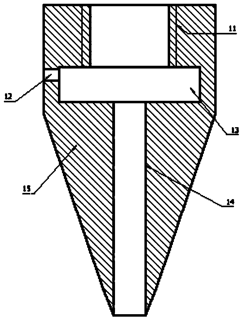
[0046] Please refer to figure 1 and figure 2 , the first outer cylinder 1 includes a first outer cylinder internal thread 11, a first infusion port 12, a first li...


PUM


Abstract

The invention discloses an electrofluid shower nozzle of a spiral micro-flow channel and belongs to the field of electrofluid printing. The electrofluid shower nozzle comprises a metal probe and a first outer cylinder. The metal probe comprises a needle body, a needle point and a circular truncated cone. The needle body is a cylinder. A first external thread is arranged on the circumferential surface of the needle body. The needle point is arranged at the lower end of the needle body. The first external thread extends to the upper part of the needle point. The circular truncated cone is arranged at the upper end of the needle body and is coaxial with the needle body. The first outer cylinder comprises a first liquid storage tank and a probe installation hole. The first liquid storage tankis provided with a first infusion opening. The probe installation hole penetrates through the first liquid storage tank from top to bottom, so that a part of the first external thread is located in the first liquid storage tank. The diameter of the inner wall of the part, located below the first liquid storage tank, of the probe installation hole is equal to the large diameter of the first external thread and is matched with the first external thread to form a first spiral micro-flow channel. In the usage state, the needle point is located outside the lower end of the probe installation hole.The spiral micro-flow channel is formed by arranging threads on the outer surface of the probe and the inner wall of the outer cylinder, so that the scale of the needle point can be made smaller thanthat of the needle point of a traditional needle tube. As a result, the printing precision is improved.

Description

technical field [0001] The invention belongs to the field of electrofluid printing, and more specifically relates to a nozzle for electrofluid jet printing, which can realize precise control of feed flow, improve the resolution of electrofluid jet printing, and realize multi-layer coaxial jet printing. combination. Background technique [0002] The traditional inkjet printing technology mainly adopts the principle of piezoelectric and thermal bubble inkjet. Piezoelectric inkjet printing is through the shrinkage and expansion of piezoelectric crystals, so that ink is ejected from the nozzle hole. Thermal bubble inkjet printing is to heat the small ink tank to a certain extent through electric pulses, and bubbles are generated in the ink to dissipate the ink. Squeeze it out. The liquid has surface tension, and the printed droplets are larger than the nozzle outlet diameter. The printing resolution is low, and there are requirements for the concentration and viscosity of the...

Claims


Application Information

Patent Timeline
Patent Type & Authority Patents(China)
IPC IPC(8): B41J2/14B41J2/145B41J2/165
CPCB41J2/14201B41J2/145B41J2/16517B41J2002/1657
Inventor 黄永安胡金龙刘宇
Owner HUAZHONG UNIV OF SCI & TECH
Why Eureka
Try Eureka