Position transfer device on petroleum pipeline production line

A technology for oil pipelines and transfer devices, which is used in transportation and packaging, containers and containers to prevent mechanical damage, and can solve the problems of oil pipelines shaking from side to side, damage, and cost impact.

Inactive Publication Date: 2018-08-24
余瑞钊
View PDF0 Cites 5 Cited by
  • Summary
  • Abstract
  • Description
  • Claims
  • Application Information

AI Technical Summary

Problems solved by technology

[0004] In view of the deficiencies in the existing technology, the purpose of the present invention is to provide a position transfer device on the production line of the oil pipeline to solve the problem that the fixed protection of the oil pipeline is not perfect in the process of p

Method used


Image

  • Position transfer device on petroleum pipeline production line
  • Position transfer device on petroleum pipeline production line
  • Position transfer device on petroleum pipeline production line

Examples


Embodiment Construction

[0023] In order to make the technical means, creative features, goals and effects achieved by the present invention easy to understand, the present invention will be further described below in conjunction with specific embodiments.

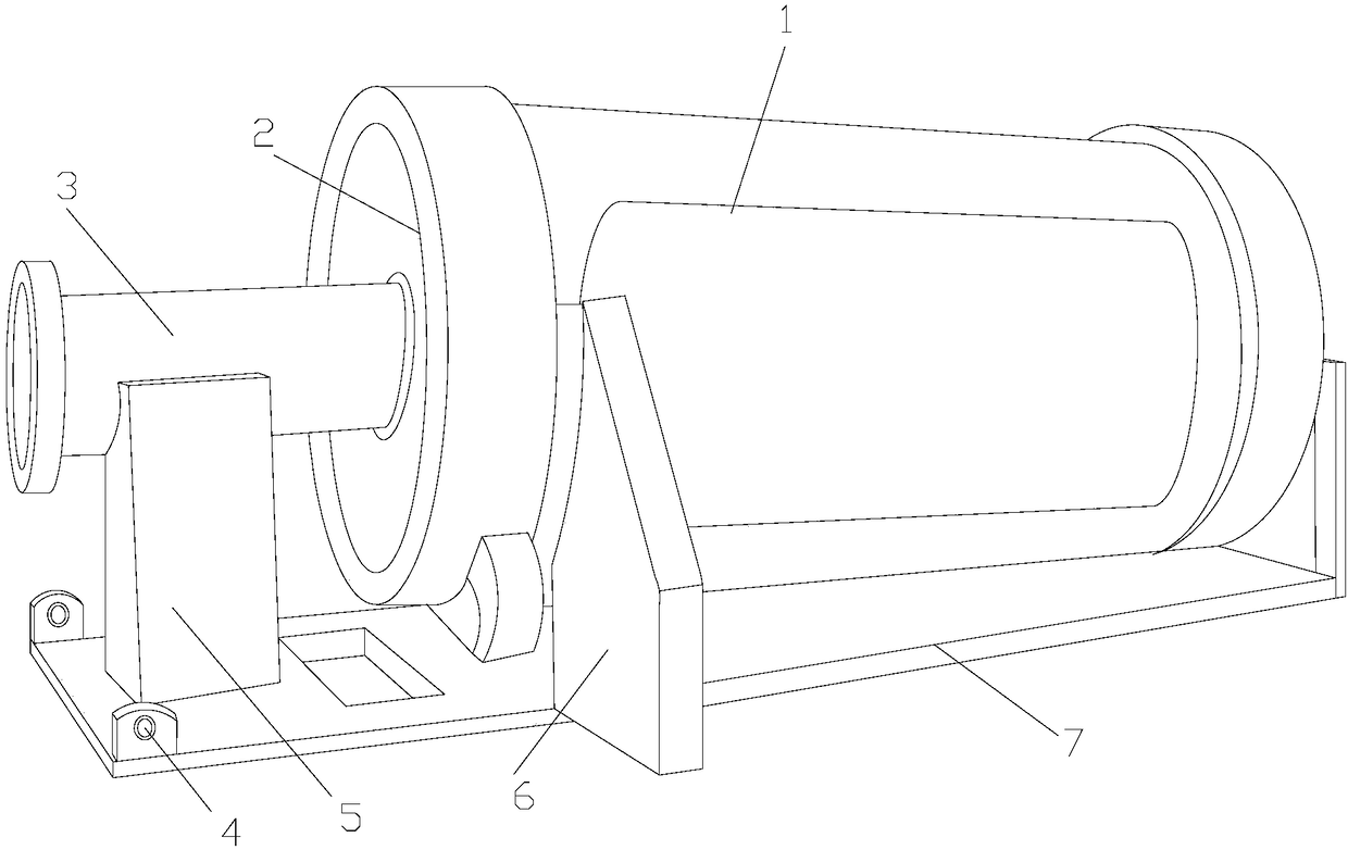
[0024] see Figure 1-Figure 5 , the present invention provides a technical solution for a position transfer device on an oil pipeline production line: its structure includes a body 1, an automatic shrinkage clamping device 2, an oil pipeline 3, a suspension ring 4, a support column 5, a stabilizing plate 6, and a bottom plate 7. The pipeline 3 is nestedly connected with the body 1, the automatic retraction clamping device 2 is installed on the left end of the body 1 by embedding, the bottom end of the body 1 is welded to the top of the stabilizing plate 6, and the top of the support column 5 Connected with the bottom of the oil pipeline 3, the top of the bottom plate 7 is provided with two lifting rings 4, and welded to each other, the bottom of t...


PUM


Abstract

The invention discloses a position transfer device on a petroleum pipeline production line. The position transfer device on the petroleum pipeline production line structurally comprises a machine body, an automatic shrinkage clamping device, a petroleum pipeline, lifting rings, a supporting column, a stabilizing plate, a bottom plate, a power device, a gear transmission mechanism, a parallel driving mechanism, a pneumatic energy transmission mechanism, a protective cover shell, a power transmission mechanism, lifting shrinkage mechanisms and clamping fixing mechanisms. According to the position transfer device on the petroleum pipeline production line, the petroleum pipeline can be effectively clamped and fixed, the problems that collision and damage are caused due to the fact that left and right swaying and instability exist in the process of the position transfer of the petroleum pipeline are avoided, and the transportation work of the staff is facilitated.

Description

technical field [0001] The invention relates to a position transfer device on an oil pipeline production line, which belongs to the technical field of production equipment. Background technique [0002] The position transfer device on the oil pipeline production line includes a bracket, a motor located inside the bracket, a connecting arm located above the motor, and a grabbing assembly located at the left end of the connecting arm. The motor is placed vertically. The output end passes through the support plate, the output end of the motor is provided with a reducer, the upper end of the reducer is provided with an output shaft, the upper end of the output shaft is sleeved on the right end of the connecting arm, and the output shaft and the connecting arm are connected by a key; the cross section of the connecting arm is rectangular, and the left end is open. There is a first through hole, and the first through hole is circular. [0003] However, in the process of transferr...

Claims


Application Information

Patent Timeline
IPC IPC(8): B65D25/10B65D81/07
CPCB65D25/10B65D81/07
Inventor 余瑞钊
Owner 余瑞钊
Why Eureka
Try Eureka