

Hanger shunting device for clothing manufacture hanging system
A hanger and hanging technology is applied in the field of devices that realize rail transition on opposite sides, and can solve the problems of poor working stability of the distribution and transfer device, dropping the hanger or sticking of the hanger, unfavorable for the hanger to change rails, etc., and achieves a simple structure and smoothness. Good, small hindering effect
- Summary
- Abstract
- Description
- Claims
- Application Information
AI Technical Summary
Problems solved by technology
Method used
Image

Examples
Embodiment Construction
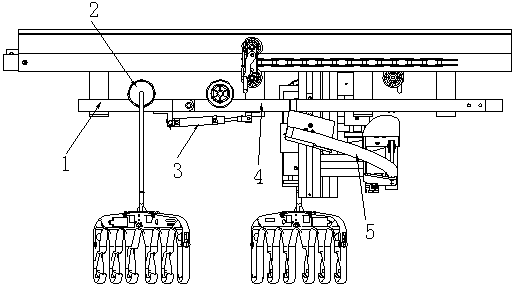
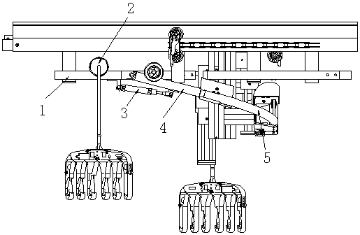
[0028] Combined with the accompanying drawings in the specification, the rail transfer device is arranged on the opposite sides of the ring rail 1 of the garment hanging system, usually on the opposite sides of the ring rail 1 in the transverse direction, and is used to place the clothes hanger between the opposite sides of the ring rail 1. The rails are turned so that some hangers directly cross the opposite sides of the ring track 1 without detours on the ring track 1 .
[0029]In order to adapt to the setting of the switch rail device, the ring rail 1 itself is in the form of a non-closed structure, and openings and partitions are respectively provided on opposite sides of the ring rail 1 . On the side of the opening on the ring rail 1, there is a rail changing rod 4 hinged, the outer end of the rail changing rod 4 is a free end, and the middle position of the rail changing rod 4 is connected to the cylinder 3, driven by the cylinder 3, the rail changing The outer end of th...
PUM
 Abstract
Description
Claims
Application Information