
Structure model impact loading device

A technology of structural model and loading device, which is applied in the direction of measuring device, machine/structural component test, impact test, etc., can solve the problems of poor application flexibility, narrow application range, single structure and composition, etc., and achieve high use flexibility and applicable The effect of wide range and low operation threshold

Active Publication Date: 2018-08-24
HEFEI UNIV OF TECH
View PDF12 Cites 2 Cited by
  • Summary
  • Abstract
  • Description
  • Claims
  • Application Information

AI Technical Summary

Problems solved by technology

Although there are more and more researches on impact loading experiments of structural models, the structure of the loading device is relatively simple and the application flexibility is poor, so on the one hand, the function of the loading device is not fully used, and the data measurement accuracy is relatively low. On the other hand, it also leads to the poor applicability of the current loading device, the narrow scope of application, and the inability to effectively test and simulate arbitrary impact load loading. caused great difficulty

Method used


Image

  • Structure model impact loading device
  • Structure model impact loading device
  • Structure model impact loading device

Examples


Embodiment Construction

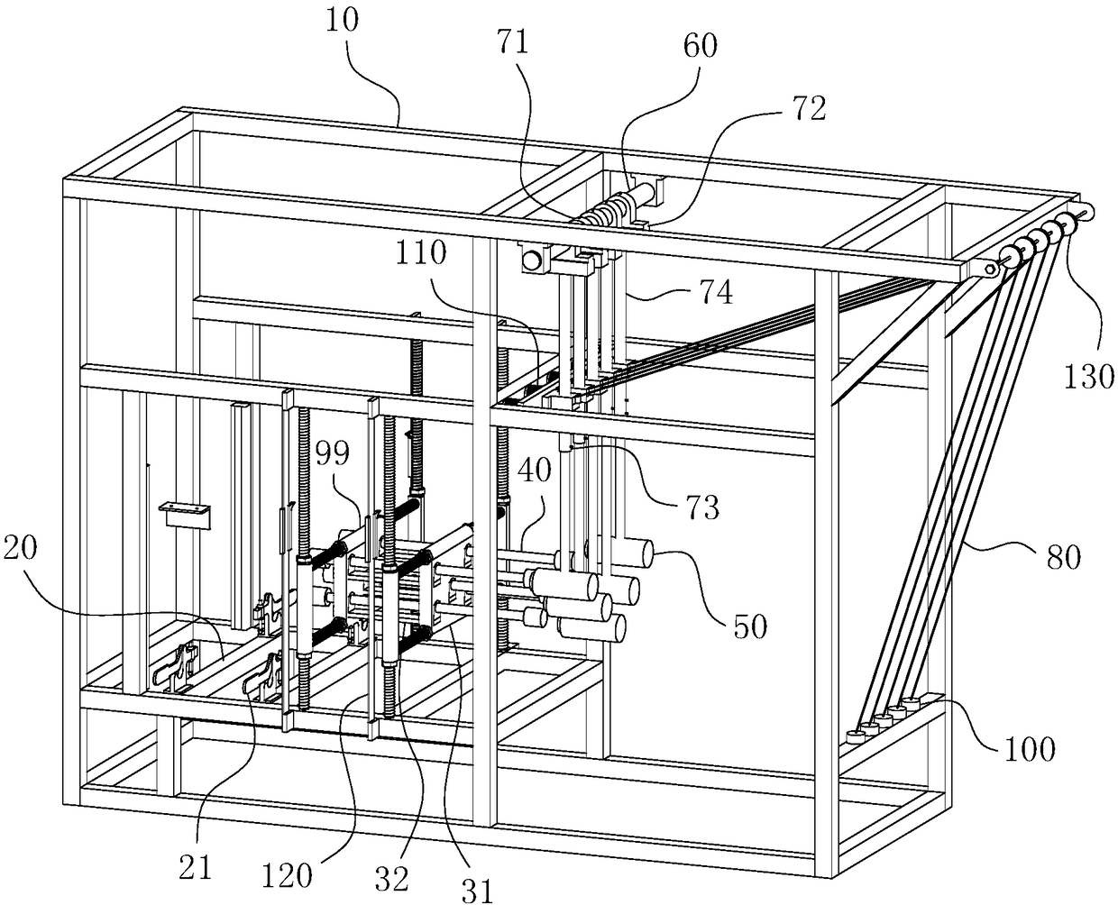
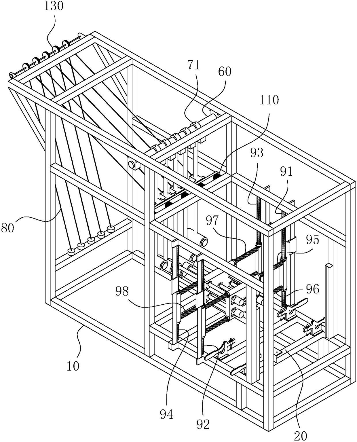
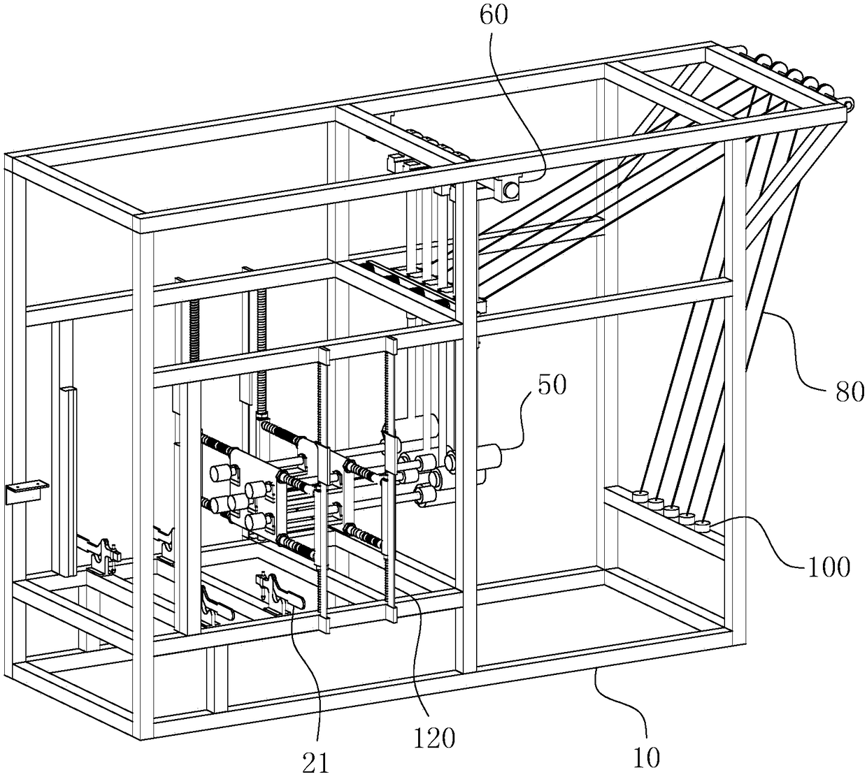
[0026] For ease of understanding, combined here Figure 1-4 , the concrete structure and working mode of the present invention are further described as follows:

[0027] The specific structure of the present invention is as Figure 1-4 As shown, the main frame 10 is used as a carrier, and various functional parts are inserted into the square frame-shaped main frame 10, so as to achieve the purpose of single-point or multi-point impact on any point of the structural model.

[0028] In specific operations, such as figure 1 As shown, an operating table 20 with a tiger clamp 21 is arranged on the lower left side of the main frame 10, so as to realize the function of fixing the position of the structural model. A laser rangefinder is arranged on the left side of the console 20 to accurately monitor the deformation of the structural model after being hit. The right side of the console 20 constitutes an assembly area for placing the adjustment seat and the displacement adjustment a...


PUM


Abstract

The present invention belongs to the technical field of structure model impact loading, and especially relates to a structure model impact loading device. The device comprises a main frame, an impactmodule, a regulation seat and a displacement regulation module. The regulation seat comprises vertical plates and connection rods, installation holes penetrate the plate surfaces of the vertical plates, transmission rods penetrate the installation holes, the four transmission rods are distributed at four corner ends of the vertical plates in a square plate shape; an impact module is a pendulum bob; the device comprises a horizontal sliding support, a sliding rod of the horizontal sliding support is sleeved with a rotating sleeve, the horizontal sliding support is provided with a horizontal expansion valve, and the rotation sleeve penetrates the horizontal expansion valve to control the rotation sleeve to perform displacement motion in a horizontal direction along the sliding rod; a liftingrod is extended downwards at the outer wall of the rotation sleeve in a vertical direction, a vertical expansion valve is employed between the lifting rods and a bob rod of the pendulum bob to control the lifting rods and the bob rod to move to each other in opposite directions and move away from each other in opposite directions; and the pendulum bob controls the swing amplitude through a stay cord. The structure model impact loading device can achieve the purpose of single-point or multi-point impact at any position of a structure model.

Description

technical field [0001] The invention belongs to the technical field of structural model impact loading, and in particular relates to a structural model impact loading device. Background technique [0002] With the development of social science and technology, many application components often need to undergo modeling and structural model impact loading experiments to verify their structural reliability before they are put into actual production. The correct evaluation of the structural reliability of the structural model must be based on accurate and comprehensive test data. Although there are more and more researches on impact loading experiments of structural models, the structure of the loading device is relatively simple and the application flexibility is poor, so on the one hand, the function of the loading device is not fully used, and the data measurement accuracy is relatively low. On the other hand, it also leads to the poor applicability of the current loading dev...

Claims


Application Information

Patent Timeline
Patent Type & Authority Applications(China)
IPC IPC(8): G01M7/08
CPCG01M7/08
Inventor 王辉郭广帅万宜品戚玉奎
Owner HEFEI UNIV OF TECH
Learn More