
A cam-driven braille display module

A driving type and cam technology, which is applied in the field of cam-driven braille point display modules, can solve the problems of restricting the popularization of piezoelectric ceramic type braille point displays, large volume, and high manufacturing cost of parts, and achieve good social benefits and application value. Easy to popularize and promote, light weight effect

Active Publication Date: 2019-12-03
ZHEJIANG SCI-TECH UNIV
View PDF4 Cites 0 Cited by
  • Summary
  • Abstract
  • Description
  • Claims
  • Application Information

AI Technical Summary

Problems solved by technology

Since then, companies in Japan and Germany have developed braille display devices of 20 square meters and 40 square meters using piezoelectric ceramic sheets, and continuously optimized the structure to make the performance of piezoelectric ceramic sheets more stable. Low power consumption, fast refresh speed, light weight, and can provide a large supporting force, but there are also shortcomings: the production and processing process is cumbersome, and the manufacturing cost of parts is high, which limits the popularity of piezoelectric ceramic braille displays
At the beginning of the 20th century, Fung-Huei Yeh and others from the Department of Mechanical and Mechatronic Engineering of Tamkang University in Taiwan, China developed an electromagnetic Braille display device, because the electromagnetic Braille contact drive mechanism has a fast refresh rate and high reliability. High, favorable price, easy to manufacture and maintain, and can provide a large supporting force, etc. Since then, it has been continuously researched in some countries such as South Korea and China, but the whole device has a large current demand and high power consumption, so it needs to be installed with a cooling device , larger volume

Method used


Image

  • A cam-driven braille display module
  • A cam-driven braille display module
  • A cam-driven braille display module

Examples


Embodiment Construction

[0026] The present invention will be further described below in conjunction with the drawings.

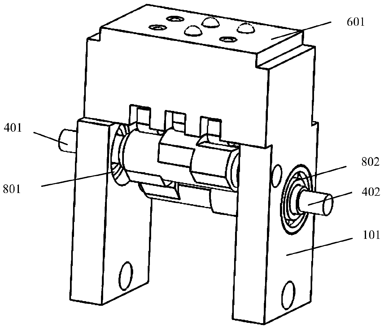
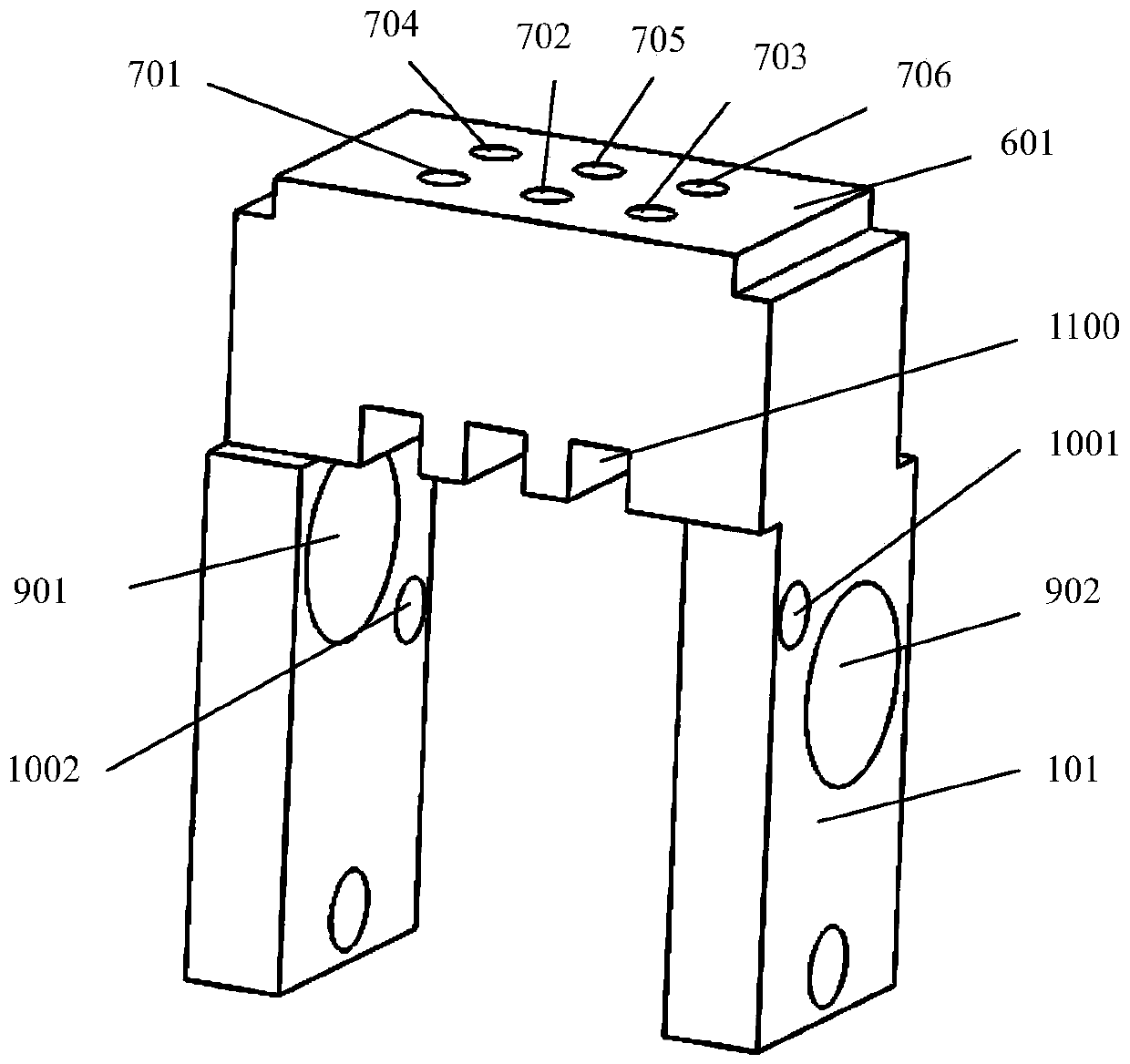
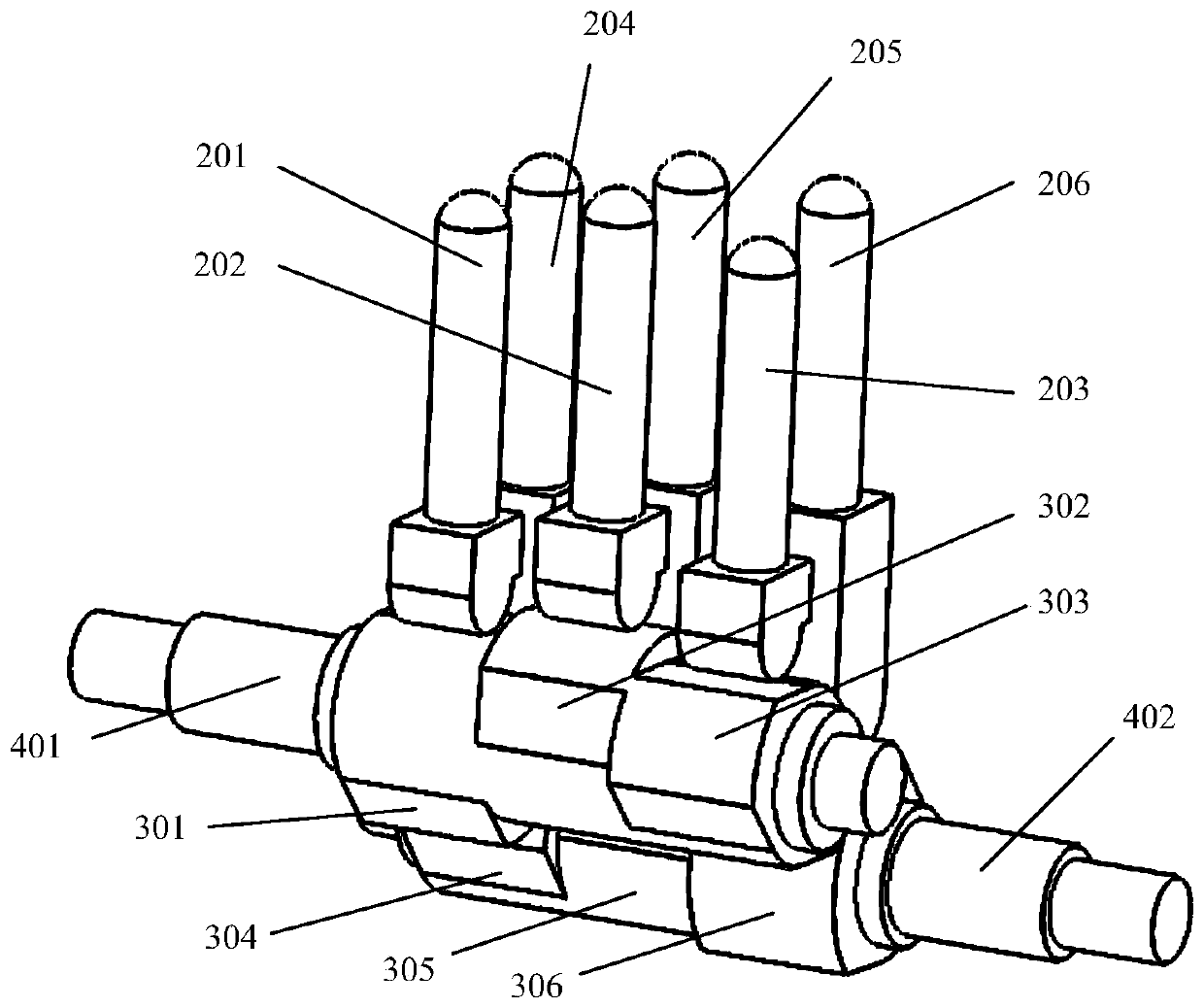
[0027] Reference Figure 1 ~ Figure 6 , A cam-driven braille point display module, comprising a support frame 101, a touch panel 601, contact pins, camshafts and a driver, the touch panel 101 is installed on the upper end of the support frame, the touch panel 601 is provided There are three rows and two columns with a total of six contact pin mounting holes. The contact pins are provided with three rows and two columns and a total of six contact pin mounting holes are installed in the corresponding contact pin mounting holes. Each contact pin has a clearance fit with the contact pin mounting hole. A camshaft is arranged under the contact pins, and each camshaft is provided with three cams. The six contact pins correspond to the six cams one by one, and the lower end of each contact pin is always in contact with the contour of the corresponding cam; the camshaft It is rotatably install...


PUM


Abstract

The invention discloses a braille salient point module of a cam drive type, and the module comprises a support frame, a touch plate, a touch pin, camshafts, and a driver. The touch plate is mounted atan upper end of the support frame, and the touch plate is provided with six touch pin mounting holes in three rows and two columns. There are six touch pins in three rows and two columns, and the touch pins are in the corresponding touch pin mounting holes. Each touch pin is in a clearance fit with the corresponding touch pin mounting hole, and one camshaft is arranged at the lower part of each column of tin pins. Each camshaft is provided with three cams, and the six touch pins are corresponding to the six cams in a one-to-one manner. The lower end of each touch pin is always in contact withthe contour of the corresponding cam. The camshafts are rotatingly installed on the support frame, and are connected with the driver. A pair of camshafts are used for driving the six touch pins to form 64 modes of contact arrangement for one square, and the module is an important part of a braille salient point device and a braille reading device, and is suitable for the generation of all types of braille characters in all languages.

Description

Technical field [0001] The present invention relates to the technical fields of mechanical engineering and electronic engineering, in particular to a cam-driven braille point display module. Background technique [0002] According to statistics from the World Health Organization (WHO) in 2010, there are about 39 million blind people in the world, and most blind people live in low- and middle-income countries. China has the largest number of blind people in the world, with more than 600 blind people as of 2012 The number of blind people in China will increase substantially by 2020. Therefore, for such a large and important group of blind people, society needs to give them care and support, and they also urgently need a good learning environment and cultural education. [0003] Blind people cannot learn and read like ordinary people. Their reading methods include auditory reading and touch reading. Tactile reading with fingers has fast reading speed and good information discriminati...

Claims


Application Information

Patent Timeline
IPC IPC(8): G09B21/00
CPCG09B21/004
Inventor 吴跃成杨文珍刘培君竺志超胡旭晓吴新丽
Owner ZHEJIANG SCI-TECH UNIV
Learn More