
Control method of battery case in electric vehicle

An electric vehicle and control method technology, applied in battery temperature control, secondary battery, battery pack components and other directions, can solve the problems of cooling fan consuming battery capacity, poor cooling effect, reducing battery effective utilization efficiency, etc. Safety performance and service life, the effect of enhancing the cooling effect

Active Publication Date: 2018-08-24
IANGSU COLLEGE OF ENG & TECH
View PDF10 Cites 15 Cited by
  • Summary
  • Abstract
  • Description
  • Claims
  • Application Information

AI Technical Summary

Problems solved by technology

[0003] Purpose of the invention: The purpose of the invention is to solve the problems of poor heat dissipation when the fan suction cooling structure is used for the existing battery box, the heat dissipation fan consumes the battery capacity, and reduces the effective utilization efficiency of the battery, etc., and provides an electric vehicle battery The control method of the box is to design the battery box into two parts: the main body of the battery box and the water-cooled box body, which are separated by a high thermal conductivity aluminum plate; the cooling scheme of the battery box includes natural air cooling, forced air cooling, water cooling and heat pipe cooling

Method used


Image

  • Control method of battery case in electric vehicle
  • Control method of battery case in electric vehicle
  • Control method of battery case in electric vehicle

Examples


Embodiment Construction

[0023] The technical solutions of the present invention will be further described in detail below in conjunction with specific embodiments.

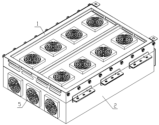
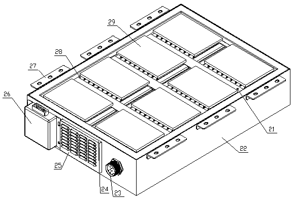
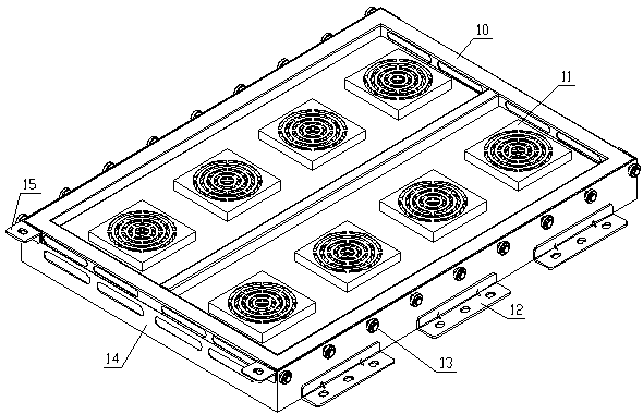
[0024] Such as figure 1 , figure 2 , image 3 , Figure 4 As shown, an electric vehicle battery box according to the present invention includes a battery pack 28, a water cooling assembly 29, a high thermal conductivity aluminum plate 3, a heat pipe radiator 4, a battery box (including a battery box main body 2, a cooling box 1), Control box 26, electrical connection port 23, cooling fan (side cooling fan 5, top cooling fan 11), thermocouple 21, etc.

[0025] Such as figure 1 , figure 2 , image 3 , Figure 4 As shown, the battery box is composed of a cooling box 1 and a battery box main body 2, which are connected by locking bolts through the first connecting angle plate 12 and the second connecting angle plate 27; the high thermal conductivity aluminum plate 3 is placed in the cooling box 1 Between the main body of the batter...


PUM


Abstract

The invention discloses a control method of a battery case in an electric vehicle. The battery case includes: a battery pack, a water cooling assembly, a high-heat-conductive aluminum plate, a heat pipe radiator, a battery case body (comprising a battery case main body and a cooling box body), a control box, wiring ports, two heat radiation fans, a thermal couple, etc. The battery case body is composed of the battery case main body and the cooling box body in a connection manner of bolts through connecting angle plates. The cooling box body is provided with a heat radiation fan, a guiding pulley and a positioning buckle. The heat pipe radiator is fixed to the high-heat-conductive aluminum plate. The battery pack, the water cooling assembly and the thermal couple are arranged in the batterycase main body. The control box and the wiring ports are arranged on one side of the battery case main body and the windward side of the battery case main body is in a louver structure, which is provided with a wind filter plate. A heat radiation fan is arranged on the other side of the battery case main body. In common situation, the battery pack in the battery case is cooled through natural wind cooling, water cooling and heat tube radiation. If the temperature controller monitors that the temperature of the battery pack exceeds optimum threshold value, Heat radiation fans at the air outletof the battery case main body and the cover plate of the water cooling box body are controlled to start, thus enhancing cooling effects.

Description

technical field [0001] The invention relates to a battery box, in particular to a control method for the battery box of an electric vehicle. Background technique [0002] Lithium-ion batteries have become the dominant power source for electric vehicles and hybrid vehicles because of their specific energy, specific power, low self-discharge, good cycle performance, and environmental friendliness. Pure electric vehicles powered by lithium-ion batteries have become a hot spot in international competition. International mainstream car companies will vigorously promote electric vehicles based on lithium-ion batteries in the next few years. However, lithium-ion batteries generate a lot of heat during use, which will cause the temperature of the battery to rise and the temperature between the batteries in the battery pack to be uneven, which will affect the performance of the battery, and even affect the life and safety of the battery in severe cases. At present, the heat dissipat...

Claims


Application Information

Patent Timeline
Patent Type & Authority Applications(China)
IPC IPC(8): H01M2/10H01M10/613H01M10/625H01M10/63H01M50/249
CPCH01M10/613H01M10/625H01M10/63H01M50/20Y02E60/10
Inventor 巫邵波唐菊唐向清王建萍史云霞
Owner IANGSU COLLEGE OF ENG & TECH
Learn More