Eureka AIR delivers breakthrough ideas for toughest innovation challenges, trusted by R&D personnel around the world.

Orthopedic surgery steel wire twisting device

An orthopedic surgery and wire technology, applied in the field of medical devices, can solve the problems of labor and inconvenience in operation, and achieve the effects of simple structure, convenient operation and easy mastery.

Pending Publication Date: 2018-08-28
THE AFFILIATED HOSPITAL OF TRADITIONAL CHINESE MEDICAL TO SOUTHWEST MEDICAL UNIV
View PDF0 Cites 0 Cited by
  • Summary
  • Abstract
  • Description
  • Claims
  • Application Information

AI Technical Summary

Problems solved by technology

[0003] At present, when the steel wire is screwed and fixed, there are the following problems: clinically, after the steel wire is installed, the end of the steel wire is usually clamped by a vise, and then the vise clamp is rotated to tighten the steel wire like a "twist", which is inconvenient and laborious to operate.

Method used


Image

  • Orthopedic surgery steel wire twisting device
  • Orthopedic surgery steel wire twisting device
  • Orthopedic surgery steel wire twisting device

Examples


Embodiment 1

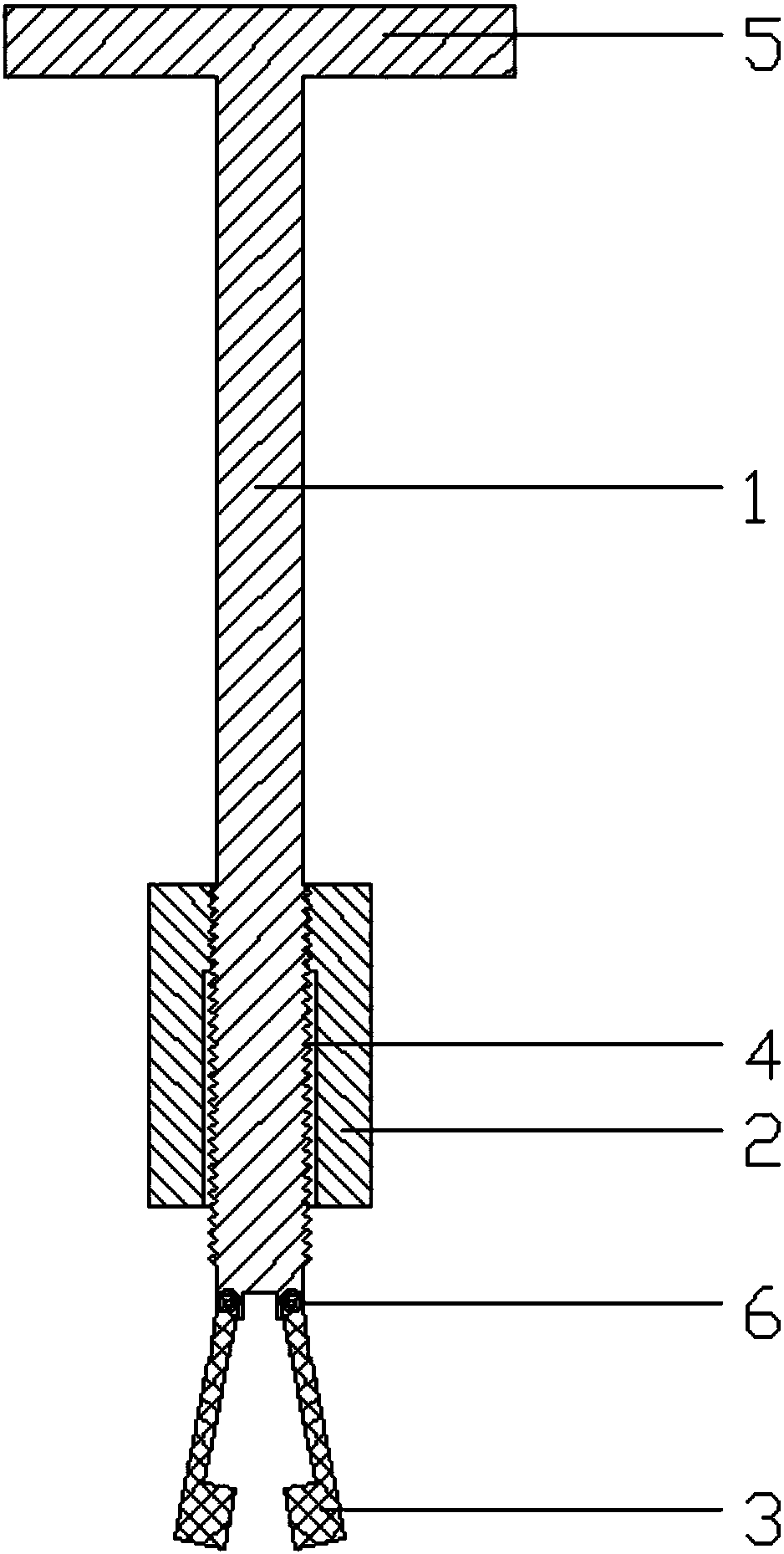
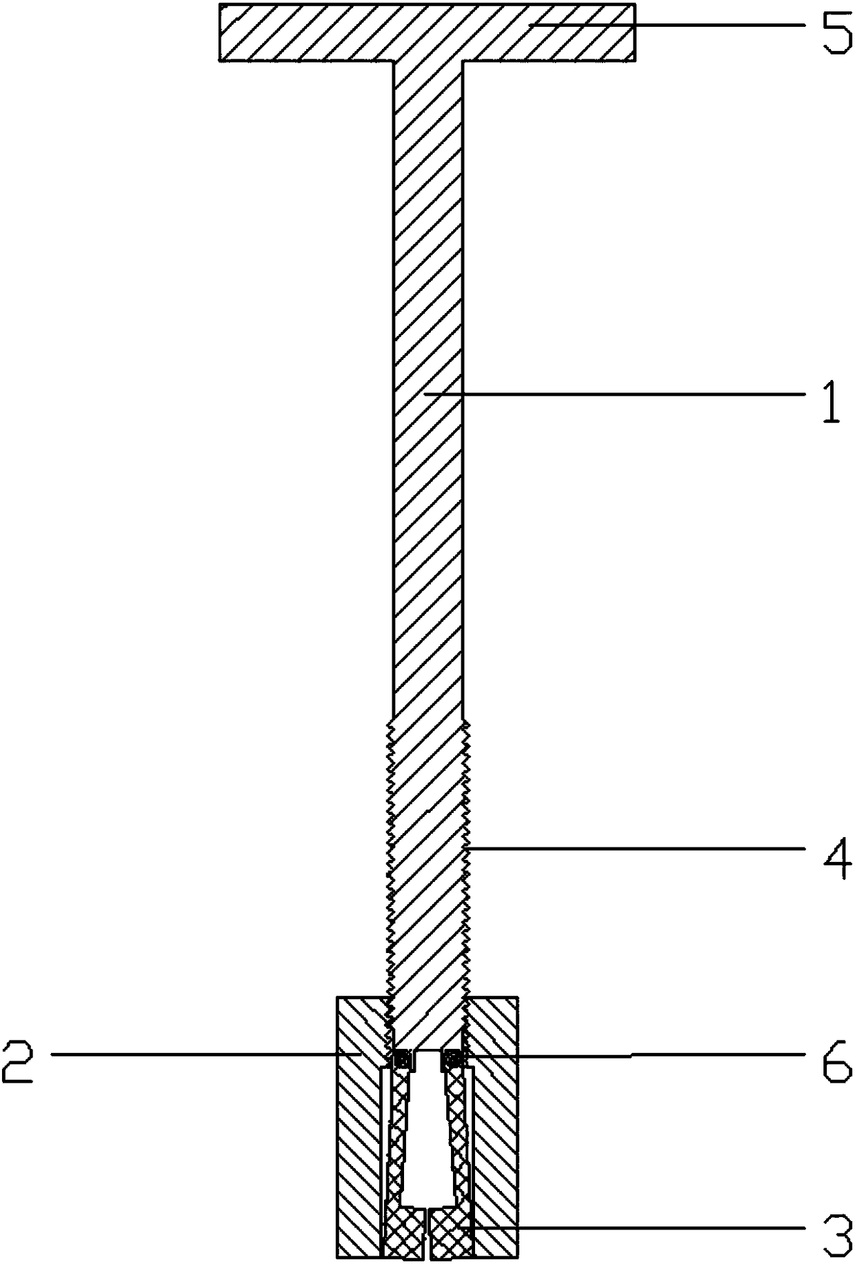
[0028] like figure 1 As shown, the orthopedic surgery steel wire twister disclosed in this embodiment, the transmission arm 1, the sleeve 2 and the clamping device, the rear end of the transmission arm 1 is provided with a handle 5, the front end of the transmission arm 1 is provided with a clamping device, and the clamping device A three-lobe occluder in the prior art can be selected. In this embodiment, the clamping device includes three clamping arms 3, and the three clamping arms 3 are opened under the action of elastic force; the sleeve 2 is set on the transmission arm 1, and the transmission arm 1 is provided with an external thread 4, and the external thread 4 extends To the front end of the transmission arm 1, the rear part of the sleeve 2 has an internal thread adapted to the external thread 4. The sleeve 2 is threadedly matched with the transmission arm 1 .

[0029] The front part of the sleeve 2 is in clearance fit with the transmission arm 1, and the three clampi...

Embodiment 2

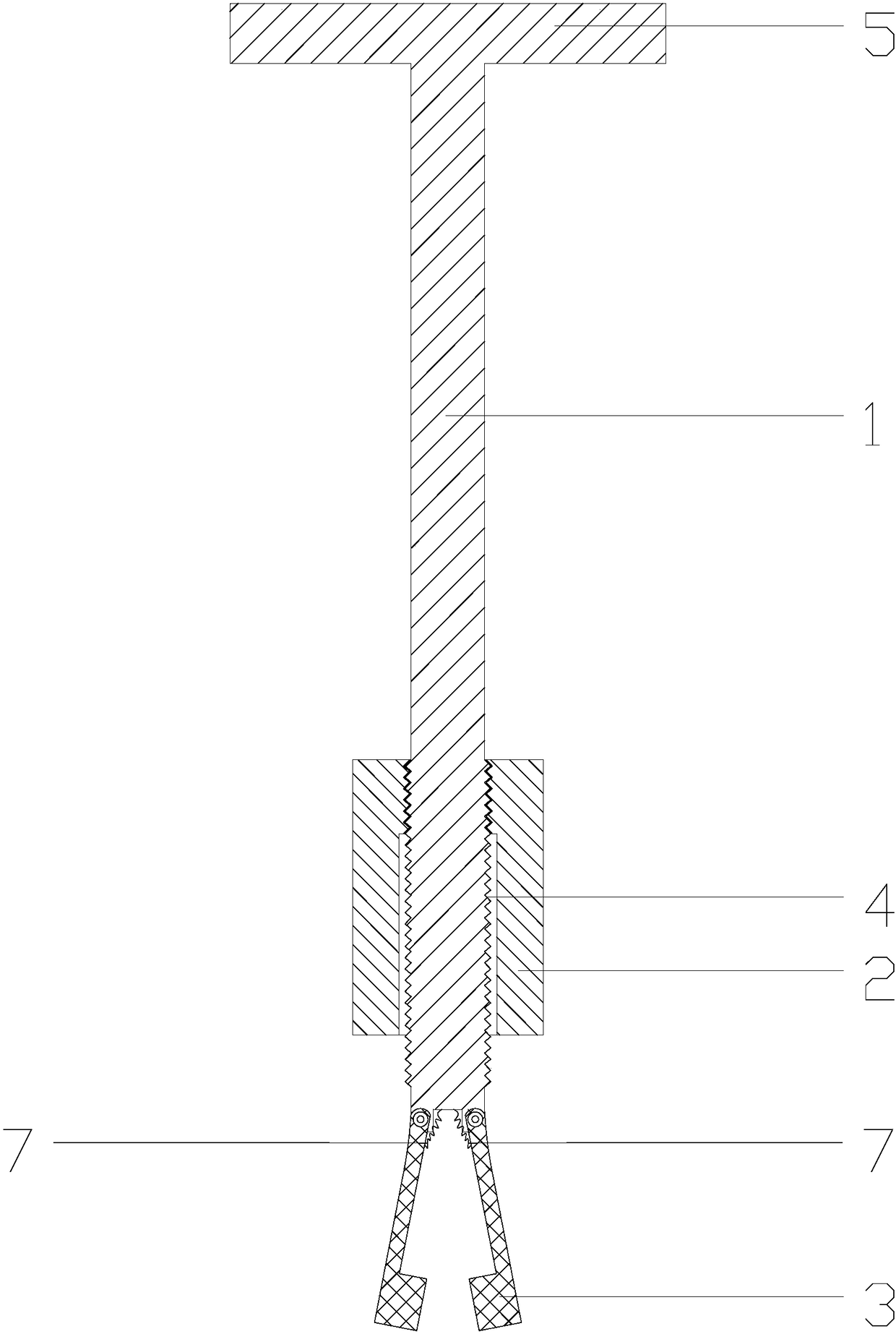
[0033] The difference between this embodiment and embodiment 1 is: as image 3 As shown, the elastic force to open the clip arm 3 is provided by the coil spring 7 . One end of clamp arm 3 is hinged with transmission arm 1 , one end of coil spring 7 is connected with clamp arm 3 , the other end of coil spring 7 is connected with transmission arm 1 , and coil spring 7 is located inside clamp arm 3 .

Embodiment 3

[0035] The difference between this embodiment and embodiment 1 is: as Figure 4 As shown, the elastic force to open the clamp arm 3 is provided by the clamp arm 3 itself. The clamping arm 3 is an elastic piece, and one end of the clamping arm 3 is fixedly connected to the transmission arm 1, and can be fixed by screws or welding. Three clamp arms 3 can be manufactured in one piece.

[0036] like Figure 5 As shown, the sleeve 2 is rotated to move forward along the transmission arm 1, and the sleeve 2 gradually presses the clamping arm 3 inward until the clamping device is clamped. Because the sleeve 2 is threadedly matched with the transmission arm 1, the clamping device can be kept in a clamped state, and the tail end of the steel wire can be firmly clamped. Subsequently, the handle 5 of the rotation T can twist the steel wire or remove the steel wire. Finally, reversely rotate the sleeve 2 so that it moves backward along the transmission arm 1. Breaking away from the ex...


PUM


Abstract

The invention relates to an orthopedic surgery steel wire twisting device. The orthopedic surgery steel wire twisting device comprises a transmission arm, a sleeve and clamping device and is characterized in that a T-shaped handle is arranged at the rear end of the transmission arm; the clamping device is arranged at the front end of the transmission arm and comprises three clamp arms, and the three clamp arms spread under elastic force; the sleeve sleeves the transmission arm, the rear of the sleeve is coordinated with the transmission arm in a threaded manner, the front of the sleeve is in clearance fit with the transmission arm, and the three clamp arms can be allowed to clamp by moving the sleeve to the front end of the transmission arm; by rotating the sleeve to allow the sleeve to move forwards along the transmission arm, the sleeve inwardly squeezes the clamp arms to allow the clamping device to clamp; by reversely rotating the sleeve to allow the sleeve to move backwards alongthe transmission arm, the clamp arms recover to the spread state under elastic force when the squeezing force of the sleeve is removed, and the orthopedic surgery steel wire twisting device can be taken away. The orthopedic surgery steel wire twisting device is simple in structure, high in operability, easy to master and convenient to operate and labor-saving during steel wire twisting or the reverse twisting of twisted steel wires.

Description

technical field [0001] The invention relates to the technical field of medical instruments, in particular to a wire twister for orthopedic surgery. Background technique [0002] In orthopedic surgery, the treatment of fractures generally requires internal fixation. In some special fractures, such as patella fractures and olecranon fractures, Kirschner wires and steel wires can be used to fix them with tension bands. It can also be temporarily fixed by steel wire binding, which not only has a good effect, but also saves costs for patients, and is widely used in trauma orthopedics. [0003] At present, when the steel wire is screwed and fixed, there are the following problems: clinically, after the steel wire is installed, the end of the steel wire is usually clamped by a vise, and then the vise clamp is rotated to tighten the steel wire like twisting a "twist", which is inconvenient and laborious to operate. Contents of the invention [0004] The invention aims to provide ...

Claims


Application Information

Patent Timeline
IPC IPC(8): A61B17/88
CPCA61B17/8861A61B2017/564
Inventor 张磊扶世杰周鑫刘洋
Owner THE AFFILIATED HOSPITAL OF TRADITIONAL CHINESE MEDICAL TO SOUTHWEST MEDICAL UNIV
Why Eureka
Eureka Blog
Learn More