
Cutting platform and cutting system

A cutting platform and cutting system technology, applied in the direction of welding/cutting auxiliary equipment, auxiliary devices, laser welding equipment, etc., can solve the problem of sticking to the surface of the workpiece 12 to be cut and the surface of the abutment body 11, platform damage, increased maintenance costs, etc. problem, achieve the effect of reducing the risk of adhesion, avoiding damage and improving quality

Inactive Publication Date: 2018-08-28
WUHAN CHINA STAR OPTOELECTRONICS SEMICON DISPLAY TECH CO LTD
View PDF5 Cites 10 Cited by
  • Summary
  • Abstract
  • Description
  • Claims
  • Application Information

AI Technical Summary

Problems solved by technology

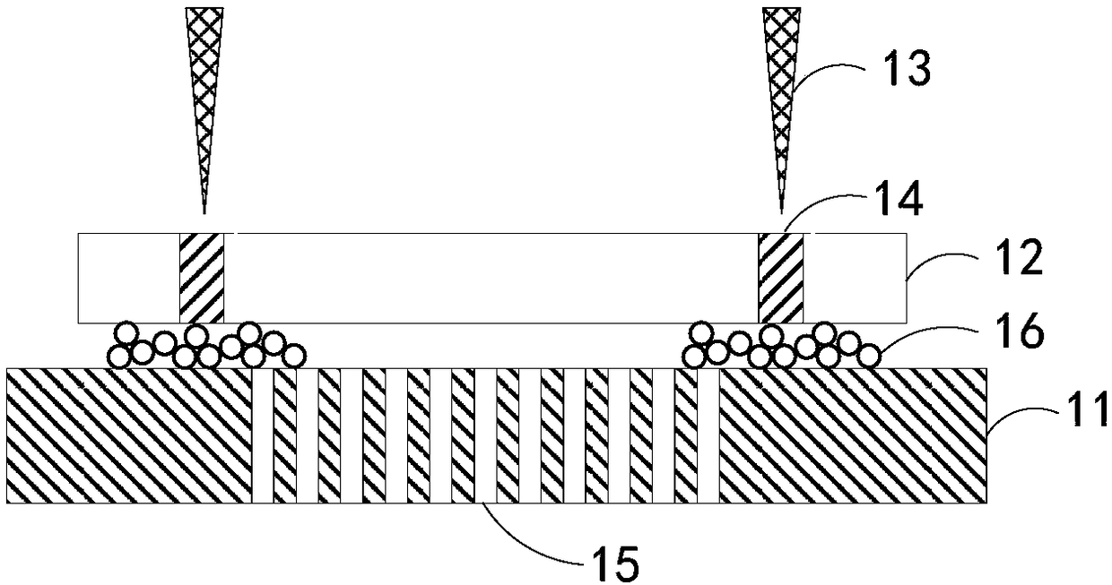
Existing laser cutting abutments usually include an abutment body 11 and an adsorption hole 15 arranged on the abutment to fix the position of the workpiece 12 to be cut and start laser cutting, and the residual debris 16 produced by cutting cannot be discharged , will stick to the surface of the workpiece 12 to be cut and the surface of the abutment body 11, which will seriously affect the product quality and equipment production efficiency. At the same time, the laser will also damage the platform during long-term production, affecting the normal operation of the equipment and increasing maintenance costs.

Method used


Image

  • Cutting platform and cutting system
  • Cutting platform and cutting system
  • Cutting platform and cutting system

Examples


Embodiment Construction

[0019] The present invention will be described in detail below in conjunction with the accompanying drawings and embodiments.

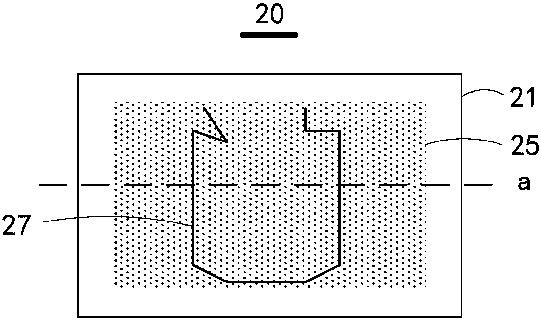
[0020] see figure 2 , is a top view structural diagram of the cutting platform of the present invention. The cutting platform 20 includes:

[0021] The platform body 21, the platform body 21 includes a first surface 211 for fixing the workpiece 22 to be cut;

[0022] The cutting groove 27 is arranged on the first surface 211 of the platform body 21, and the cutting groove 27 corresponds to the cutting line 23 issued by the cutting device (not shown in the figure);

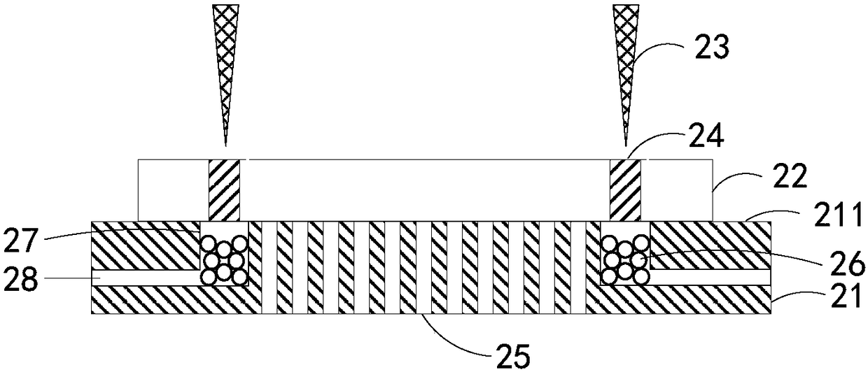
[0023] combine image 3 , image 3 It is a schematic diagram of the cross-sectional structure of the cutting platform of the present invention.

[0024] along figure 2 The middle dotted line a cuts off the cutting platform 20, and the platform body 21 includes at least one dust removal channel 28, one end of the dust removal channel 28 communicates with the cutting groove 27, and t...


PUM


Abstract

The invention discloses a cutting platform and a cutting system. The cutting platform comprises a platform body, a cutting groove and at least one dedusting channel, wherein the platform body comprises a first surface which is used for fixing a to-be-cut piece; the cutting groove is formed in the first surface of the platform body, and the cutting groove corresponds to a cutting line sent by a cutting device; and the at least one dedusting channel is formed in the platform body, one end of the dedusting channel communicates with the cutting groove, and the other end of the dedusting channel isconnected with a dedusting device and is used for discharging residues which are generated when the to-be-cut piece is cut by the cutting line and fall in the cutting groove. In the mode, the productquality can be increased, and the production efficiency of equipment can be improved.

Description

technical field [0001] The invention relates to the field of display technology, in particular to a cutting platform and a cutting system. Background technique [0002] With the continuous progress of the display industry, more and more display devices of different styles appear in people's field of vision. In the prior art, when making display devices, large-scale display panels or display Cutting, and then use the cut small display panel or display substrate to make a display device, which requires very high cutting precision and quality. [0003] The current cutting process usually uses laser cutting technology. Such as figure 1 As shown, during laser cutting, the piece to be cut 12 is fixed on the base body 11 of the laser cutting base, and then the cutting area 14 of the piece to be cut 12 is cut with a laser line 13 . Existing laser cutting abutments usually include an abutment body 11 and an adsorption hole 15 arranged on the abutment to fix the position of the wor...

Claims


Application Information

Patent Timeline
Patent Type & Authority Applications(China)
IPC IPC(8): B23K26/38B23K26/70B23K37/04
CPCB23K26/38B23K26/702B23K37/0408
Inventor 吕洋
Owner WUHAN CHINA STAR OPTOELECTRONICS SEMICON DISPLAY TECH CO LTD
Learn More